Key takeaways
- Size the gland hole to the gland thread and the plate to the cable: an M50 gland needs 25 mm of edge margin, so the smallest practical gland plate for four entries is roughly 300 × 250 mm, not the 200 × 150 mm that gets drawn.
- An armoured 4C × 95 mm² cable of about 57 mm outside diameter needs 450 mm of bend radius, which sets the plinth height and decides bottom versus side entry before the panel is drawn.
- Mask the gasket land: 0.16 mm of powder across two mating faces changes the plate-to-frame gap, and a seal that bears on film rather than on steel creeps and weeps within two monsoons.
- Every spare hole in a cable entry panel is a leak and a noise path. Draw a blanking plate for unused entries rather than a knockout.
- Bond the gland plate to the canopy with a welded M8 or M10 earth boss and a conductor of at least 50 mm²; the door gasket, the powder coat and the hinge are not an earth path.
The cable entry panel is the smallest piece of sheet metal on a DG canopy and the one most likely to bring the canopy back. A 200 × 150 mm plate with three holes in it decides whether the set stays dry through a monsoon, whether the earth bond holds under fault current, and whether the acoustic enclosure that was tested in a yard still meets its figure on site.
The failure is almost never the steel. Genset cable entry panel design fails on a gland hole 12 mm from an edge, a plate at 1.5 mm that dishes when the gland is tightened, a gasket land that was powder coated because the mask was forgotten, or a knockout left open on a set that only needed two cables. Each of those is a drawing decision, and each costs a service visit to correct.
This guide sets out genset cable entry panel design for the way canopies are built and installed in India: gland plate geometry, the space a cable needs, the coating and masking that make a gasket work, earthing, and the inspection that catches a weeping entry before dispatch. It comes from the canopy and base frame work we run for Mahindra Powerol, where the entry panel is made on the same line as the louvres and access doors.
What decides the size of a cable entry panel?
The cable decides it, in this order: outside diameter, bend radius, gland size, then plate stiffness. Not the space left on the canopy.
Start with the largest cable. An armoured four-core 95 mm² copper cable is about 55–57 mm across. Its minimum bend radius for a fixed installation is around eight times that diameter, or roughly 450 mm. That single number sets how far the cable has to travel from the ground into the gland, which sets the plinth height, and the plinth height decides whether the entry can be in the base or has to move to the side of the canopy.
Then the gland. An M50 cable gland has a body over 60 mm across and a locknut that needs a wrench swing; the hole needs 25 mm of clear material around it to hold the gasket flat and to take the tightening torque without dishing the plate. Four such entries plus a control cable on a 200 mm wide plate does not fit, whatever the outline drawing shows.
Last, stiffness. A 1.5 mm plate with a single M50 gland tightened to 20–25 N·m dishes visibly between the bolts. At 2.5–3.0 mm it holds within 1 mm per metre and the gasket stays seated. The plate is cut from the same laser as the rest of the canopy, so the extra 1 mm costs almost nothing in material and nothing in process.
The numbers to put on the drawing
These are the values we check a cable entry panel against before quotation. They assume CRCA or galvanised sheet, a bolted gland plate with an EPDM or neoprene gasket, and a canopy that has to hold an IP rating at the entry.
| Parameter | Typical design value | Ganesh limit or note |
|---|---|---|
| Gland plate thickness | 2.5–3.0 mm | 0.8–40 mm part range; laser cuts to 20 mm |
| Single-entry plate, small canopy | 2.0 mm | 200 T brake, 4,450 mm bed |
| Hole position tolerance | ±0.5 mm | Fibre laser; hole diameter +0.2/−0 mm |
| Clear edge margin around gland | ≥ 25 mm | Checked against locknut swing |
| Clear spacing between glands | ≥ 1.5 × gland body diameter | Wrench access, gasket land |
| Gasket land width | 12–15 mm | Masked; no coating |
| Gasket compression | 25–35% of free thickness | 10 mm bulb to 6.5–7.5 mm fitted |
| Cable bend radius, armoured | ≥ 8 × outside diameter | 450 mm for a 57 mm cable |
| Gland thread engagement | Full nut plus 2 threads | Plate plus gasket under 10 mm |
| Earth boss | Welded M8 or M10 stud | 50 mm² minimum bonding conductor |
| Earth continuity | ≤ 0.1 Ω boss to canopy frame | Checked with a micro-ohmmeter |
| Coating, external faces | 60–80 µm powder | DFT gauge per batch; cross-hatch |
| Coating inside the gland hole | None on the thread land | Mask before powder |
| Panel flatness | 1 mm per metre | ±0.5 mm general tolerance |
| IP target at the entry | IP54 or IP55 per contract | IEC 60529 defines the test, not the design |
Two of those deserve the arithmetic.
Gasket compression. A 10 mm EPDM bulb gasket is designed to sit at 6.5–7.5 mm when the plate is bolted down, a 25–35% squeeze. If the gasket land is powder coated at 80 µm, the gasket bears on film rather than on steel: the film creeps under gland load, the land is no longer flat across its 12 mm width, and the squeeze becomes uneven around the gland. The side with the least squeeze is the side that weeps. Masking a 12 mm band costs one operation and removes the variable.
Hole to edge. An M50 gland with a 60 mm body needs 25 mm of clear plate outside the hole. Put the hole 15 mm from the edge and the gasket overhangs, the locknut bears on the edge, and the plate curls. The fix at the drawing stage is a larger plate; the fix on the shop floor is a rework ticket.
Water: the entry is a drain unless it is designed as a seal
Water reaches a canopy floor from three directions — rain driven under the plinth, washdown from a hose, and groundwater on a site that floods — and all three arrive at the cable entry from below.
Four details handle it:
- Bottom entry with a drip loop. The cable rises to the gland from below, so water runs to the lowest point of the loop and drips off. A cable that goes straight up into a gland carries water into the canopy along its sheath.
- Gland sealing on the sheath, not on the armour. Specify the gland type and the sealing range against the cable's actual outside diameter. An armour gland that seals on the armour and leaves the inner sheath open lets water track inside the cable.
- A gasket with a defined groove. Draw the groove or the land, the gasket section, and the compression. A gasket called out as "neoprene 3 mm" tells nobody whether the plate will squeeze it to 2 mm or to 1 mm.
- A drain or a slope at the plinth. A canopy base frame that traps water at the entry point will find the weakest gasket within a season. Base frame detailing is covered in welded genset base frames.
One mechanical point that is often missed: the hole edge must not cut the cable. A laser-cut hole has a clean edge, but a hole that has been opened up with a file or a step drill leaves a burr on the inside face, and pulling a 95 mm² cable through it scores the sheath. Draw a 3 mm fillet or specify a bushing where the cable bears on the edge, particularly on side entries where the cable turns immediately.
Noise: why the entry matters more than the panel
An acoustic canopy works on mass and on seams. ISO 8528 sets out the measurement of generating set noise, and ISO 8528-10 uses an enveloping surface around the set, which is exactly the surface a leaking gland plate sits on.
The mechanism is straightforward. Below about 500 Hz, doubling the mass of a panel gains roughly 6 dB of attenuation. That is the whole argument for 1.5 mm over 1.2 mm, and for a mineral wool liner behind a perforated skin. A hole defeats it: sound that escapes through an opening is not attenuated by the panel at all, and the opening's contribution grows faster than its area because the panel around it stops behaving as a closed boundary.
Practical rules we apply to the entry:
- No unsealed openings. Every spare hole gets a gasketed blanking plate. A bolt hole without a bolt is a leak.
- Gland plate gasket, not a bead of sealant. Sealant cracks at the first thermal cycle; a compressed EPDM gasket does not.
- Cable entry away from the exhaust side. The hottest, noisiest corner of a canopy is the last place to put a plate with holes in it.
- Keep the entry below the acoustic liner. A liner that stops above the entry leaves a path around it.
If the canopy is specified with a sound pressure level at 1 m — the usual 65–75 dB(A) band for a 100–200 kVA set — the entry detail belongs in the acoustic submission, not only in the fabrication drawing.
Coating, earthing and the couple between them
The cable entry panel is usually a separate part, bolted to a canopy that is already coated, so it has to be coated to the same system and still make electrical contact.
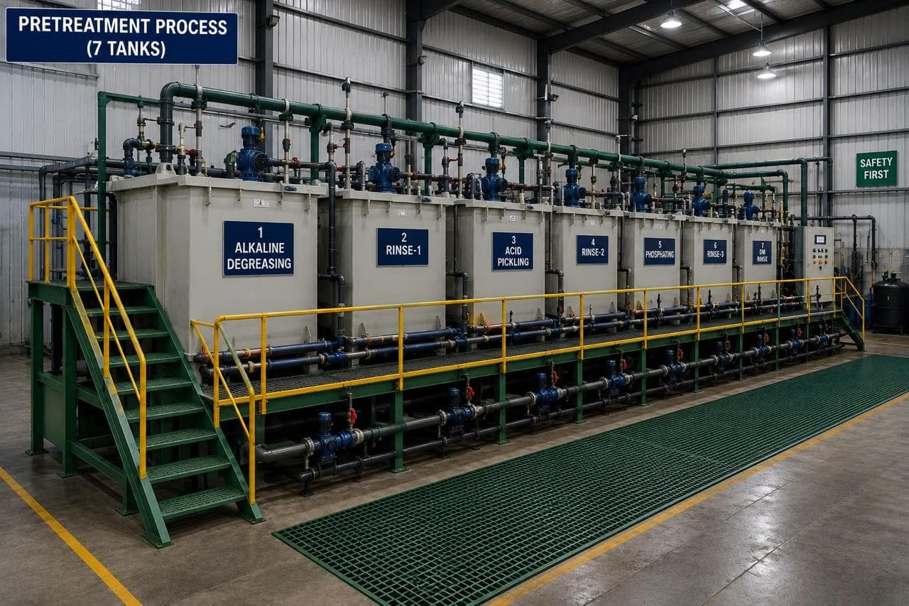
Powder at 60–80 µm in the 18 ft × 14 ft booth over seven-tank pretreatment is our standard. Three areas are masked:
- The gasket land, so the gasket compresses against steel.
- The earth boss and a 20 mm ring around it, so the bonding lug seats on bare metal.
- The gland thread land and the inside of each hole, so a gland can be fitted without chasing the thread.
Earthing is a design item, not an assembly detail. The powder coat is an insulator, the gasket is an insulator, and on some canopies the gland plate is bolted to a coated flange with coated bolts. The only reliable path is a welded boss on the plate, a welded boss on the canopy frame, and a conductor between them of at least 50 mm² with a crimped lug at each end. We check continuity from boss to frame at 0.1 Ω or less with a micro-ohmmeter and record the reading.
There is also a corrosion couple to think about. An aluminium gland plate on a steel canopy is a galvanic cell in the presence of water, and the aluminium loses. Use steel or stainless for the plate, or isolate an aluminium plate with nylon washers and a sealing gasket on both faces. The wider corrosion question for outdoor enclosures is covered in why powder coating fails on outdoor enclosures.
What Ganesh runs for canopy entry panels
The panel and its gland plate are nested with the canopy side panel and cut on the 12 kW fibre laser, whose 40 ft × 16 ft bed takes the whole side in one programme. Bending is on the 5-axis brake, and the earth boss and any stiffener are MIG welded at a manual station, with the weld cleaned before blasting because spatter holds powder off the surface.
Finishing runs through the 16 ft × 16 ft shot blast chamber, seven-tank pretreatment, then powder in the 18 ft × 14 ft booth and cure. Masking is applied before coating, DFT is read on every batch and adhesion is checked by cross-hatch. The panel is then trial-fitted to its canopy where the canopy is built as an assembly, so the gasket land and bolt holes are proved against the real flange rather than against a drawing.
We make the enclosure, not the electrical installation: glands, cables and terminations are the OEM's or the installer's scope. What we can do is supply the panel with the holes to the gland schedule, the blanking plates, the earth boss and the coating record, and we can hold that in a first article inspection for a new canopy programme. The canopy RFQ checklist lists the fields that make a canopy entry panel quotable in one pass, the seven-tank pretreatment article covers the line a masked panel runs through, and the genset and canopy hub collects the rest of the enclosure guides.
What the canopy drawing has to settle
- Cable schedule — number of cables, conductor size, outside diameter, armoured or unarmoured.
- Gland schedule — thread size, gland type, sealing range, and the hole diameter each gland needs.
- Entry position — bottom or side, with the bend radius envelope drawn, not assumed.
- Gland plate outline with hole pattern, edge margins and the bolt size to the canopy flange.
- Gasket — material, section, groove or land width, and the compression target.
- Masking zones — gasket land, earth boss ring and gland thread lands.
- Coating system with DFT and the adhesion test.
- Earthing — boss size, conductor size, lug type and the continuity limit.
- Blanking plates for every unused entry, as separate part numbers.
- IP target with the test method, and whether the entry is tested with a cable fitted or with a blanking plate.
The genset parts page covers the canopy, base frame and panel families we supply, and the laser-cut components for genset canopies article covers how those parts are nested and cut. For the forming side of the same panel, bending for genset canopies and panels covers flange heights and distortion. Send the drawing with the cable schedule through Request a quote and our engineering team will check gland spacing and sealing before the quote goes out.
When this route is not right
We do not supply cable glands, cables, lugs or termination kits. Those come from the electrical supplier, and the gland schedule has to match what they will actually fit.
We do not certify an IP rating. We can build to an IP54 or IP55 detail, perform a water-spray check on a sample, and provide the coating and gasket records, but the declaration under IEC 60529 belongs to the OEM or to a test house.
We do not weld on site. A canopy that needs an extra entry after installation gets a bolt-on plate with a gasket, sized from the cable schedule, rather than a welded patch that destroys the coating around it.
And we do not punch knockouts as a production method. Every hole is cut on the laser to the schedule, so late changes are a drawing revision, not a die change — which is the right trade for canopies built in tens and hundreds rather than tens of thousands.
Frequently asked questions
How thick should a genset cable entry panel be?
Use 2.5–3.0 mm CRCA for a gland plate carrying more than two glands, and 2.0 mm for a single-entry plate on a small canopy. Below 2.0 mm the plate dishes around a tightened M50 gland and the gasket stops sealing; a flat plate at 2.5 mm holds within 1 mm per metre.
Where should cables enter a DG canopy?
Bottom entry with a drip loop below the gland wherever the site is exposed to rain or washdown, and side entry only when the plinth height cannot give the cable its minimum bend radius. A top entry needs a weather hood and a sealed gland, and it is the entry we see leak most often.
Can I use knockouts instead of a gland plate?
Only for a single cable up to about 25 mm outside diameter. A knockout has a knife edge, removes the coating locally and leaves a hole that cannot be sealed if it is not used. Above two entries, or above 25 mm, draw a bolted gland plate with a gasket.
Does the cable entry affect canopy noise levels?
Yes. An acoustic canopy works because the panel has mass and the seams are sealed; an open or poorly sealed entry short-circuits that. Sealing spare holes and compressing the gland plate gasket back to 25–35% matters more to the measured level than adding 0.5 mm of steel.
What is the tolerance on gland hole position?
Draw ±0.5 mm, which is what we hold on the fibre laser, and add a clear edge margin of 25 mm. A gland that has to be forced onto its hole cross-threads, and a cross-threaded gland will not compress its seal evenly.
Sources and further reading
- IEC 60529 — Degrees of protection provided by enclosures (IP code) · reviewed 3 Nov 2026
- ISO standards catalogue — ISO 8528, reciprocating internal combustion engine driven generating sets · reviewed 3 Nov 2026
- ISO 2768-1 — General tolerances, linear and angular dimensions · reviewed 3 Nov 2026
Have a canopy cable entry drawing?
Send the panel drawing with the cable schedule and the IP requirement. Our engineering team checks gland spacing, bend radius and the sealing detail before quotation.
Request a quote