
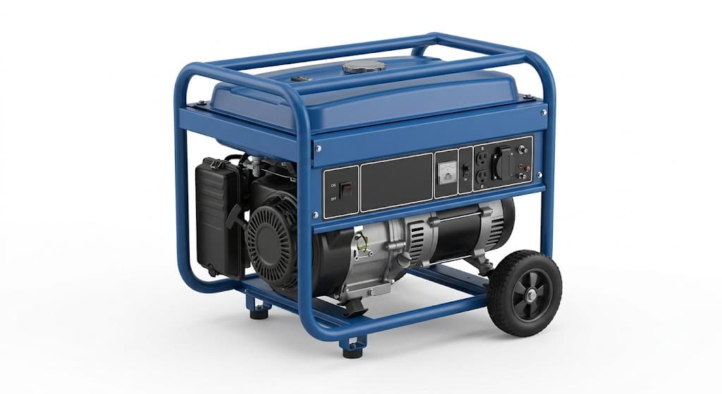
Key takeaways
- Hold the mounting face flat within 1.0 mm over 1,000 mm and the isolator hole pattern within ±0.5 mm, or the anti-vibration pads load unevenly and the canopy stops fitting the frame.
- A 6,000 mm steel frame grows about 2.8 mm for a 40 °C temperature rise, so dimension the frame at a stated temperature and never compare a shop measurement with a site measurement.
- Weld the frame square and stress-relieve it by sequence before you drill or ream isolator pads; welding after the pads are machined is the most common cause of a frame that will not sit.
- Set the four lift points so each sling leaves the vertical at no more than 45°, and specify the weld throat rather than the leg size.
A genset base frame is judged by three numbers, and none of them is weld strength: mounting face flatness, isolator hole position and lift point geometry. A frame with perfect 5 mm fillets will still be rejected if the anti-vibration pads sit 3 mm off a plane, because the engine then loads two pads instead of four and the canopy no longer closes on its hinges. Buyers who specify welded genset base frames for the first time usually write "weld as per drawing" and leave these three numbers to the supplier. That is where the rework starts.
This article sets out the geometry a frame has to hold, the distortion mechanism that moves it, the thickness and process limits that decide the route, and the fields that belong on the drawing. It is written for the design engineer who has to release a frame revision and for the manufacturing engineer who has to make the same frame for the twentieth time.
What a welded genset base frame actually controls
The frame sets the plane the engine and alternator sit on, the bolt pattern the canopy lands on, and the load path from the lifting slings into the skid. Everything bolted to it inherits its errors. An isolator that is 2 mm low puts the engine weight on three pads; the fourth pad rattles, the set vibrates, and the canopy skins start cracking at the door corners within a season.
Three dimensions do most of the damage:
- Mounting face flatness across the four isolator pads, because the pads are elastomer and cannot absorb a twisted base.
- Isolator hole centre distance, because the engine mounts are drilled in one operation at the engine plant and cannot be slotted at assembly.
- Canopy interface, usually a bolt pattern around the perimeter plus two hinge faces, because the canopy is a welded box with almost no adjustment.
Everything else, including the outside envelope and the skid underside, is easier to recover. Concentrate the inspection on the three above and the frame will fit.
Limits worth putting on the drawing
The values below are what a formed-and-welded frame can hold without a machining operation. They are written as drawing callouts, not as promises about any individual part.
| Parameter | Typical drawing value | Ganesh limit or note | What happens if it is loose |
|---|---|---|---|
| Frame material and thickness | 3–6 mm CRCA or mild steel; 8–10 mm at pads | Brake forms to 10 mm; laser cuts to 20 mm plate | Thin flanges oil-can; thick ones distort more when welded |
| Formed channel | C-section from one blank, 60–120 mm web | 200 T, 4,450 mm bed, 5-axis, Delem control | Rolled channel needs a second welding operation and a straightening pass |
| Mounting face flatness | 1.0 mm per 1,000 mm; 2.0 mm overall | ±0.5 mm typical on machined pads, by agreement | Pads load unevenly; isolator life drops |
| Isolator hole position | ±0.5 mm to the engine drawing | Fixture-drilled or laser-cut in a template | Engine will not drop onto the frame at the line |
| Frame diagonal | ±2.0 mm on a 2,000 mm square | Measured after welding, before coating | Canopy sits skew, doors bind at one corner |
| Weld size | 3–5 mm fillet, throat specified | Robotic MIG on three CLOOS cells; 30+ manual stations | Oversized fillets add heat, not strength |
| Lift point position | Four points, 20–25% in from each end | Plate and boss welded before final squaring | Sling angle exceeds 45°, legs bend |
| Coating | Seven-tank pretreatment plus powder | 18 ft × 14 ft booth; DFT checked by gauge | Paint bridges the earth point and the set floats |
| Earth continuity | Masked pad, bare metal to bare metal | Masking called out on the drawing | Failed continuity test at the customer's line |
Treat the flatness row as the one to argue about at quotation, not after first article. A frame that needs machining to hold 0.5 mm per 1,000 mm is a different part from a frame that is welded and checked.
How the frame moves while it is being welded
MIG welding puts roughly 1 kJ into every 10 mm of a 4 mm fillet, and that heat arrives in a sequence. The frame responds by shrinking along the weld as it cools, which pulls the flange towards the weld and lifts the opposite corner. Two rules keep this predictable.
Weld in a balanced sequence: opposite corners first, then the remaining two, then the long seams from the centre outwards. Never run a full-length seam from one end, because the free end accumulates the whole contraction. A 2,000 mm seam with a 4 mm fillet can pull 1.5 mm to 2.5 mm of bow into the member it is attached to, which is more than the flatness budget on a small frame.
Second, tack the frame square on a fixture that holds the diagonals, not on the floor. A flat floor is not a datum. Welding on a steel-topped fixture with adjustable stops costs fixture time once and removes the straightening step on every frame afterwards. Ganesh builds welding and checking fixtures in-house for this reason; the fixture is part of the process, not an accessory.
The temperature number that explains most site disputes
Steel expands about 11.7 × 10⁻⁶ per °C. A 6,000 mm frame measured at 22 °C in the shop and checked at 45 °C on a site in Rajasthan has grown:
6,000 × 11.7 × 10⁻⁶ × 23 = 1.6 mm
Diagonal checks double the effect because the diagonal is longer and the two directions move differently. This is why the acceptance record should state the temperature at which the frame was measured. A 1.6 mm shift is inside the ±2.0 mm diagonal band on its own, so a frame that is genuinely square can still read out of tolerance on a hot afternoon. Agree the measurement temperature, or agree that the check is done in the shop and the site check is a fit check only.
Thickness decisions that follow from the route
A formed C-section from one laser-cut blank is usually the cheapest base frame member. The blank is cut on the 12 kW fibre laser with a 40 ft × 16 ft bed, so a 4,000 mm channel can be cut flat with the isolator holes and the lift plate slots already in place, then formed in two hits on the 200 T brake. Nothing is drilled after forming, so the hole pattern cannot drift relative to the bend.
Above 10 mm the brake stops and the route changes to plate fabrication: cut on the laser up to 20 mm, or on the iron worker for 30–40 mm, then welded as a built-up section. A built-up 12 mm channel is heavier and needs more weld, but it suits sets where the skid is also the shipping base.
Canopy interface and acoustic panel fit
The base frame is also the canopy's foundation, so the two are quoted together or not at all. Three interfaces decide whether the canopy closes cleanly:
- The perimeter bolt pattern, which should be on a pitch that matches the canopy post spacing on both long sides. If the frame uses a 600 mm pitch and the canopy posts are at 750 mm, one side will need slotted holes.
- The hinge faces at the access doors, which need a flat land at least 25 mm wide behind the hinge. A hinge screwed to a thin upstand flexes and the door sags.
- The cable entry and fuel line cut-outs, which must be positioned after the isolator pattern is fixed, because the engine moves when the pads settle.
Acoustic panels do not load the frame much, but they do add mass to the canopy and change how the frame is lifted. A canopy with 50 mm acoustic infill on all four sides weighs considerably more than a weatherproof skin alone, and the lift points sized for the bare frame will not be correct for the finished set. State the lift condition: frame only, or frame with canopy and set.
What Ganesh runs on this route
Base frames and canopy structures for Mahindra Powerol follow one route: laser-cut blanks on the 12 kW machine, forming on the 200 T, 4,450 mm, 5-axis brake, fixture-controlled welding on three CLOOS robotic MIG cells and more than 30 manual MIG, spot and SPM stations, then shot blasting, seven-tank pretreatment and oven-cured powder coating; the powder booth takes a part up to 18 ft × 14 ft.
The robotic cells carry the repeat seams: the long channel-to-cross-member fillets and the lift plate welds that have to look identical on every frame. Manual stations take the access-restricted corners and the fit-up welds where the torch cannot reach. Fixtures are designed and built in the in-house tool room, so the diagonal stops and the isolator pin positions are made and maintained by the same team that runs production. Tooling is quoted separately from the piece price, which matters when a frame revision changes the fixture.
Five units across Mumbai (Vasai) and Nagpur carry the work under ISO 9001:2015 and ISO 14001:2015, with PPAP and first article inspection available where the program needs it. The genset parts page lists the canopy, frame and panel scope; the canopy RFQ checklist is the fastest way to get a complete enquiry in front of the estimating team.
What belongs on the drawing
Put these fields on the frame drawing, in this order. If a field is not on the drawing, the supplier will choose for you.
- Material grade, thickness and the surface condition of the incoming sheet.
- Mounting face flatness as a per-metre value and an overall value, with the measurement method.
- Isolator hole pattern as a positional tolerance to the engine drawing, not as a chain of dimensions.
- Frame diagonal tolerance and the temperature at which it is measured.
- Weld symbols with throat thickness; mark the welds that must be continuous and the ones that may be skip-welded.
- Lift point positions, plate thickness and the sling angle assumed.
- Masking plan: earth pads, machined faces, threaded inserts that must stay paint-free.
- Coating specification with colour reference, target dry film thickness and the adhesion test method.
- Marking and serial location, because a frame without a serial cannot be traced back to a weld record.
When a welded frame is the wrong answer
Some sets should not use a welded frame. If the genset is containerised and shipped in knocked-down form, a bolted frame that is re-assembled on site tolerates the field adjustment a welded frame cannot. If the set is a one-off prototype, a bolted or folded frame avoids a fixture that will never be used again. If the customer requires a machined skid with line-bored pad faces to 0.2 mm, that is a machining job with a welding step, and it should be quoted as such rather than squeezed into sheet metal tolerance.
We do not offer in-house machining centres, structural load testing or type approval against generator set standards. Frames that need a certified load test come with the customer's test house or a third-party inspector, and the drawing should say so. Being clear about that boundary early is cheaper than discovering it at first article.
Cost drivers a buyer should question
Four things move the price of a base frame more than material. Fixture cost is the first: a new pattern of isolator holes means a new set of location pins, and that is a one-time charge. Second is weld length, because robotic time is charged by the metre of seam and a 4 mm fillet over 12 m is not the same as a 3 mm fillet over 6 m. Third is the number of formed members against built-up members, since every extra weld adds distortion control work. Fourth is coating, where a frame that fits the 18 ft × 14 ft booth in one hang is cheaper than one that must be coated in two operations.
Ask for those four numbers separately, and two quotations become comparable. The quotation comparison guide sets out the line items that should appear. The category hub at genset, canopy and acoustic enclosures carries the rest of this cluster, including canopy and panel bending and weld distortion control in frames.
A frame that is flat, square, drilled once and lifted from four planned points is a boring part to make. That is the point. Send the current revision with the isolator pattern and the lift condition to request a quote and the route can be reviewed against the real geometry before the order is placed.
Frequently asked questions
What flatness should I specify on a genset base frame mounting face?
Specify 1.0 mm per 1,000 mm and 2.0 mm overall on a 3,000 mm frame, measured on the pads that carry the anti-vibration mounts. Tighter than 0.5 mm per 1,000 mm is possible but needs machining or a post-weld flattening operation, which changes the price and the lead time.
Why does my base frame fit in the supplier's shop and not at site?
Usually temperature. A 6,000 mm steel frame expands about 2.8 mm across a 40 °C swing between a cold shop and a hot site. If the diagonal is measured at 20 °C and checked at 45 °C, the numbers will not agree even when the frame is square.
Should the base frame be welded or bolted?
Weld it when the frame is a repeat item and the canopy is built on the same fixture every time. Bolt it when the set is shipped in a container and the frame must be re-assembled on site, because a bolted frame tolerates field adjustment that a welded frame cannot.
What thickness should a genset base frame channel be?
Most industrial sets use 3 mm to 6 mm CRCA or mild steel channels formed on a press brake, with 8 mm to 10 mm plates at the isolator and lift points. The 200 T brake forms up to 10 mm, so a formed C-section is usually cheaper than a rolled channel plus welding.
Can you paint the frame after the engine is mounted?
No. Pretreatment and oven cure happen before assembly, because the seven-tank line and the curing oven cannot take an assembled set. Mask the earth points and any machined pad on the drawing so they stay conductive.
Sources
- ISO 2768-1 — General tolerances for linear and angular dimensions without individual tolerance indications · 3 Nov 2026
- Bureau of Indian Standards — IS 2062 hot rolled structural steel, and IS 513 cold reduced steel sheet · 3 Nov 2026
- ASTM B117 — Standard practice for operating salt spray (fog) apparatus · 3 Nov 2026
Send the frame drawing for a route review
Include the isolator hole pattern, the mounting face flatness callout, the lift point positions and the canopy bolt-up interface. We will come back with the weld sequence, fixture approach and coating route before quoting.
Send a drawing