Key takeaways
- A part that dries between two tanks has already failed the conversion stage: keep the surface wet from tank 1 to tank 6, with a transfer time under about 30 seconds.
- Rinse quality is a conductivity number, not a look: hold the demineralised final rinse below about 30 µS/cm and read it every shift, because a part cannot be inspected for salt by eye.
- A 2 m² hanger carrying 0.1 L/m² of drag-out puts 0.2 L of tank 1 chemistry into tank 2 on every transfer; 300 such transfers move 60 L, so an overflowing rinse is the only control that holds.
- Coating weight is measured gravimetrically to ISO 3892 on a test coupon, not judged from the colour of the part, and it is the number an auditor will ask to see against the batch record.
- Blind cavities and upward-facing pockets hold air or liquid and produce a bare patch that no bath correction can fix; a 6 mm drain hole at the lowest point is a drawing decision.
A seven tank pretreatment line decides coating life in the twenty minutes before the part reaches the powder booth, and it does so through four variables that move together: bath temperature, chemical concentration, dwell time and the volume of liquid the part carries out with it. Change any one and the conversion coating changes, even when every tank is present and every gauge reads normal.
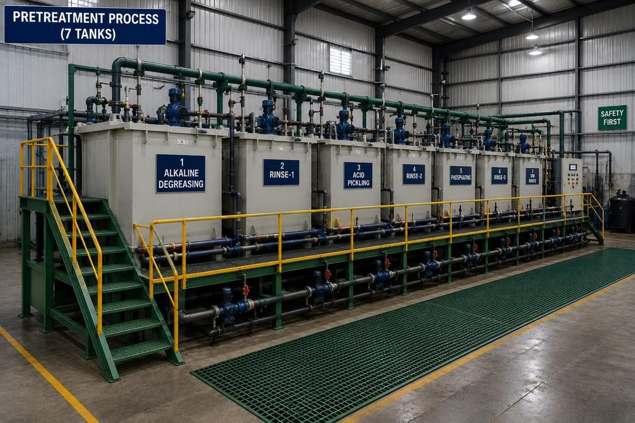
This is the physical walkthrough. It follows the part from the load station to the dry-off exit, shows where temperature and concentration are actually held, and sets out the record an auditor will ask to see. The specification and defect-diagnosis side — film thickness, cure, what each stage prevents and how to troubleshoot a blister — belongs to seven-tank pretreatment process explained, and is not repeated here.
Values in the table are typical working ranges for an alkaline-cleaner and zinc-phosphate line. The approved plant process and the customer specification govern the set points that a line actually runs.
What does the part physically see on the line?
The part is loaded on a jig or hanger, and the hanger is what travels. On a hoist line the transfer creeps from tank to tank; on a conveyor line it passes continuously over a row of tanks with fixed dwell in each. Either way, the geometry that matters is the same: the part hangs over a drip zone between two tanks, and whatever runs off it lands either in a drain tray or in the tank behind it.
Three physical rules come out of that layout. First, the part must stay wet from tank 1 to tank 6, because a film that dries on the surface concentrates the previous chemistry and starts flash rust on bare mild steel. Second, the part must be oriented so that no upward-facing pocket holds air, because a pocket of air is a patch the chemistry never touches. Third, the jig contact points are bare metal by definition and have to land somewhere the drawing can accept.
Load density is the quiet variable. A hanger packed with parts shields the faces in the middle of the bundle: the spray cannot reach them, the conversion bath circulates poorly around them, and the coating weight on the shielded face ends up lower than the coupon that was tested at the start of the shift.
Where temperature and concentration are actually held
Temperature is held by a heat exchanger or an immersion heater under thermocouple control, and the number that matters is the tank reading at the moment the part goes in, not the set point on the controller. A 3,000 L degreasing tank loses heat every time a cold hanger goes in and gains it slowly through the exchanger, so a line that runs batches with gaps will show a sawtooth on the temperature chart rather than a flat line. A band of about ±2–3 °C around the set point is normal on a well-controlled tank; a 10 °C drop across a shift is a control problem, not weather.
Concentration is held by titration, not by topping up. Degreaser is measured as free and total alkalinity, the conversion bath as free acid, total acid and accelerator, and the ratio between the two acid numbers matters more than either one alone. The titration tells you how much chemistry is present; it does not tell you how much oil is present, which is why a tank can titrate perfectly and still stop cleaning. Oil is removed by an overflow weir and a skimmer on the surface, and the weir has to be set high enough to take the floating layer out rather than let it settle back onto parts.
The line, stage by stage
The table gives the working condition, the control check and the physical note for each stage. Read the dwell column as a range that the approved process sheet fixes for a specific substrate; aluminium and galvanised steel take a different chemistry through the same seven tanks.
| Stage | Typical bath condition | Temperature | Typical dwell | Control check | Ganesh limit or note |
|---|---|---|---|---|---|
| 1 Degrease | Alkaline cleaner, 1–3% working strength | 50–60 °C | 3–5 min | Free and total alkalinity, oil separation | Seven-tank line in-house; skimmed overflow on the cleaning tank |
| 2 Rinse | Town water, overflowing, spray then dip | Ambient | 30–60 s | Overflow rate, pH rise | Spray ahead of the dip cuts carry-over into tank 3 |
| 3 Activation | Mild alkaline or acid conditioner | Ambient to 40 °C | 30–90 s | pH, bath age, turbidity | Sets crystal density; a skipped stage shows as patchy adhesion |
| 4 Conversion | Zinc phosphate or zirconium | 35–45 °C zinc; ambient zirconium | 2–4 min | Free and total acid, accelerator, coating weight | Coating weight checked gravimetrically where the drawing requires it |
| 5 Rinse | Town water, overflowing | Ambient | 30–60 s | Conductivity of the water leaving the stage | Fed by counterflow from the final rinse |
| 6 Final rinse | Demineralised water | Ambient | 30–60 s | Conductivity, DI plant output | Demineralised rinse, not tap water |
| 7 Dry-off | Forced-air oven | 60–90 °C | 3–5 min | Surface dry, no flash rust, no water marks | Part must be dry before the powder booth |
| Hanger and jig | Coated steel contacts, stripped on schedule | — | Per load | Contact cleanliness, build-up | Coating build-up on a jig insulates the earth path |
The conversion stage is where the line earns its keep, and it is the stage most often run outside its window because it is the slowest. At the top of the temperature range the coating forms fast and coarse; at the bottom it forms slowly and thin. Coating weight, measured by dissolving the layer off a weighed coupon to ISO 3892, is the only honest check on which of those two happened. Colour is not a check: a zinc phosphate coating ranges from light grey to dark grey on the same bath depending on the steel.
Rinse cascade: conductivity is the control number
Rinse quality is managed as a cascade, not as seven independent tanks. Clean demineralised water enters tank 6, tank 6 overflows into tank 5, and tank 5 overflows to drain. Tank 2 runs on town water with a continuous overflow. That arrangement means the dirtiest water is always in front of the cleanest part of the process and the cleanest water is always against the part just before it dries.
The controlling measurement is conductivity in the final rinse, because dissolved salts conduct and everything else in the rinse is either water or a solid that will be filtered or settle. Hold the final rinse below about 30 µS/cm for a general powder line; a plant that also runs aluminium or a drawing with a salt limit will often hold it under 10 µS/cm. A reading that climbs through the shift means the DI plant is falling behind its resin regeneration or a valve is passing town water.
Drag-out is what pushes that number up, and it can be counted. A flat sheet drains to a film of roughly 0.1 L/m²; a fabricated frame with returns and welds carries more, because liquid sits in every corner. Take a 2 m² hanger: it carries about 0.2 L of tank 1 chemistry into tank 2 on every transfer. Over a 300-part shift that is 60 L of cleaner, oil and dissolved soil entering a rinse that may only hold 800 L. Without an overflow, the rinse becomes a weak cleaner by lunchtime and the part leaves tank 2 carrying the film the activation stage was meant to work on instead.
Soluble salt on the finished part is measured with the Bresle method to ISO 8502-9, which returns a surface density in mg/m² as sodium chloride. Where a drawing or paint system specifies a salt limit, that test is the one that answers it; a rinse conductivity reading is the line's leading indicator, not the acceptance evidence.
Dwell time, drainage and the transfer
Dwell is specified per stage and held by the transfer system, and it is the variable a busy line erodes first. A conveyor that is sped up to clear a backlog takes dwell out of every tank at once. A hoist operator who lifts a hanger early to make room takes it out of one. Neither change shows on a bath log, and both change the coating.
Drainage time between tanks should be long enough that the part has stopped dripping before it crosses the next tank's edge — typically 5–15 seconds on a hoist line. A hanger that is still streaming when it passes over tank 3 puts tank 2 water into tank 3, and the same thing happens in reverse if the drain tray is not set under the transfer path. On a line with fixed drip trays, the tray is the control; on a hoist line, the drip time is written into the operating sheet.
Parts that cannot drain are the persistent problem. A closed box section with no low-point hole holds liquid through every stage, then releases it during dry-off and the powder cure. The fix belongs on the drawing, not on the line: a 6 mm hole at the lowest point of a closed section, placed where water will not collect in service, removes the source permanently.
Dry-off and the hand-off to the booth
Dry-off is a forced-air oven that removes the surface water without heating the part enough to oxidise it. The exit condition is simple to state and easy to check: the part is dry at the jig contact and inside every return, there is no water mark, and there is no flash rust on a sheared edge. A part that leaves wet carries moisture into the powder booth, where it flashes to steam under the film during cure and lifts the coating.
The gap between dry-off and the booth is part of the line. A part that sits for an hour in a humid shop after drying picks up a moisture film again, and a part handled with bare hands picks up skin oil at the edges. Both are invisible and both show up as adhesion loss. The clean, dry part goes into the booth on the same jig it dried on, which is also why jig maintenance belongs in the line schedule.
What an auditor looks at on the line
An auditor walking a pretreatment line is trying to establish one thing: whether the parts coated yesterday were made under the conditions the process sheet requires. That breaks into a short list of evidence.
- The batch record against the production count. A log with one reading per shift for a line that ran three shifts and four colour changes is a finding, because no reading covers most of the parts.
- Limits written on the record. A sheet that records a temperature but no minimum and maximum cannot be judged in breach, so it cannot demonstrate control.
- Titration consumables in date and a calibrated burette. A titration performed with expired reagent is an unverified result.
- Conductivity meter calibration and DI plant output. The probe is the only instrument standing between a salt film and the powder.
- Coating weight records where the drawing calls for them. A coupon result with the batch number on it, measured to ISO 3892.
- Jig condition. Stripped contacts, no build-up, and a stripping interval that appears in the maintenance plan.
- Downstream confirmation. Film thickness measured to ISO 2178 with the magnetic method on five points per part, adhesion results per batch, and a first-article record that ties the two together.
- Chemical storage, spill containment and effluent records. The effluent treatment plant is part of the line's licence to run, not a separate department.
- Hanger loading against the work instruction. Overloaded jigs on the day of the audit tell the auditor what happened on the days nobody was watching.
The audit finding that repeats across plants is not a missing tank. It is a record system that captures the easy numbers and skips the ones that change the coating: coating weight, accelerator, final-rinse conductivity and drain time between stages.
How Ganesh runs pretreatment and coating
Ganesh runs a seven-tank pretreatment line ahead of an 18 ft × 14 ft electrostatic powder booth, with a separate wet paint booth, a curing oven and a 16 ft × 16 ft shot blast chamber for scale and weld discolouration on heavier fabrications. Parts from the press shop, the laser and the weld cells converge on the same line, which is what keeps a coated assembly consistent when it contains a pressed bracket, a laser-cut panel and a welded frame. Dry film thickness is checked with a DFT gauge and adhesion by cross-hatch test in house, and the route sits inside the paint shop capability.
The line also carries an effluent treatment plant, and both ISO 9001:2015 and ISO 14001:2015 apply to how the chemistry, the waste and the records are handled. The surface treatment and coating hub indexes the articles on cleaning, adhesion, cure and outdoor failure.
What the drawing has to give the line
The line can only run what the geometry allows. Put these on the drawing or in the RFQ pack, and the walkthrough above stops being a source of surprises:
- Substrate and grade, because aluminium, galvanised and CRCA take different chemistry through the same tanks.
- The service environment, so the line knows whether the coating weight target is the standard one.
- Drainage: a low-point hole in every closed section, and the position of the drain if the part has a preferred orientation.
- Hanging points or the faces where a jig mark is acceptable, agreed before the first batch rather than after it.
- Masked features: threads, earth points, mating faces and bores that must stay conductive.
- Any salt, coating weight or film thickness limit that must be evidenced, with the standard it will be tested to.
When the line cannot take the part
Some parts should not go through a seven-tank line, and saying so is cheaper than coating them badly. A fabrication larger than the tank opening cannot be dipped, so it moves to a spray route with a different pretreatment sequence. A closed assembly with trapped volumes, or a part that mixes aluminium and steel in a permanent joint, will not give a consistent coating through an immersion line. A part with a 2 mm gap between two flanges cannot be wetted properly at 60–80 µm of powder, because the chemistry cannot get in and the powder cannot either.
Where any of those apply, the honest answer at quotation is a different finish or a design change. The powder coating cost estimator shows what film thickness and masking do to the per-part cost when a drawing's requirement is being challenged, and the degreasing stage is worth reading if the part arrives with heavy drawing oil or a rust-preventive film.
Send the drawing with substrate, environment and the standard the finish must meet. The engineering team will name the tanks, the film target and the evidence the batch record will carry, before the part is quoted.
Frequently asked questions
How long does a part spend in a seven tank pretreatment line?
Plan on 20–35 minutes from loading to the dry-off exit on a typical alkaline-cleaner line: 3–5 minutes degreasing, 30–90 seconds in each rinse and activation stage, 2–4 minutes in the conversion tank. Transfer and drainage time between tanks adds a further 10–15 minutes across the line.
Why does the final rinse need demineralised water?
Tap water carries dissolved salts, and the dry-off oven leaves them on the surface as a mineral film. That film sits between the conversion coating and the powder, so adhesion and corrosion resistance both fall. A demineralised rinse held below about 30 µS/cm removes most of the carry-over before the part reaches the oven.
Can a part dry between tanks without harm?
No. A wet film that dries on uncleaned or rinsed steel leaves a concentrated residue of the previous chemistry and starts flash rust on bare mild steel within minutes. The part should stay wet from tank 1 to tank 6, which is why transfer time and drip time are written into the line's operating sheet rather than left to the operator.
What does a pretreatment auditor ask for first?
The batch record that links a production lot to the bath readings taken while that lot ran: temperature, titration result, rinse conductivity and coating weight. A log filled in once a week for a line that runs daily is the finding that follows.
Does a bigger tank give a better coating?
No, but a bigger tank is slower to change. A 3,000 L tank responds to a chemistry addition over tens of minutes, so temperature and concentration drift less between checks. Small tanks react quickly in both directions and need shorter control intervals, not a different chemistry.
Sources
- ISO 8502-9:1998 — Tests for the assessment of surface cleanliness, field method for the conductometric determination of water-soluble salts · 3 Nov 2026
- ISO 3892:2000 — Conversion coatings on metallic materials, determination of coating mass per unit area, gravimetric methods · 3 Nov 2026
- ISO 2178:2016 — Non-magnetic coatings on magnetic substrates, measurement of coating thickness, magnetic method · 3 Nov 2026
Have a part that has to survive the coating line?
Send the drawing with substrate, service environment and any standard the finish must meet. We return the pretreatment route, the film target and the inspection record the line will sign.
Request a coating quote