
Key takeaways
- Keep hole centre at least 2.5 × material thickness plus inside radius away from the bend line, or the hole ovalises on the brake at 3 mm and above.
- Specify ±0.5 mm on the cut profile as the default; reserve tighter callouts for bolt patterns that locate a guide-rail clip or a safety-gear mount.
- Order the route as cut, deburr, form, fixture-weld, then coat; welding before bending a frame stile adds 3–6 mm of drift over a 2,000 mm upright.
- Ask for the first-article record to include the diagonal measurement, not just the outside length — frame squareness fails diagonally before it fails on any single dimension.
A car frame that measures correct on every outside dimension can still fail fit-up at the guide rails. The reason is usually a datum the laser never owned: a hole pattern positioned from a cut edge that moved 1 mm on the brake, or a diagonal that grew 4 mm when the stile was welded after forming instead of before. Laser-cut elevator frame sections are cheap to cut and expensive to correct once they are welded.
The number that decides the route is the hole-to-bend distance. Below 2.5 × material thickness plus inside radius, the hole deforms as the bend forms, and no amount of inspection after the fact recovers the position. For a 4 mm stile bent over a 4 mm inside radius, that is 14 mm from the bend line to the hole centre, minimum. Design inside that and the drawing should expect a drilled or reamed hole after forming.
What a frame section has to hold before it is cut
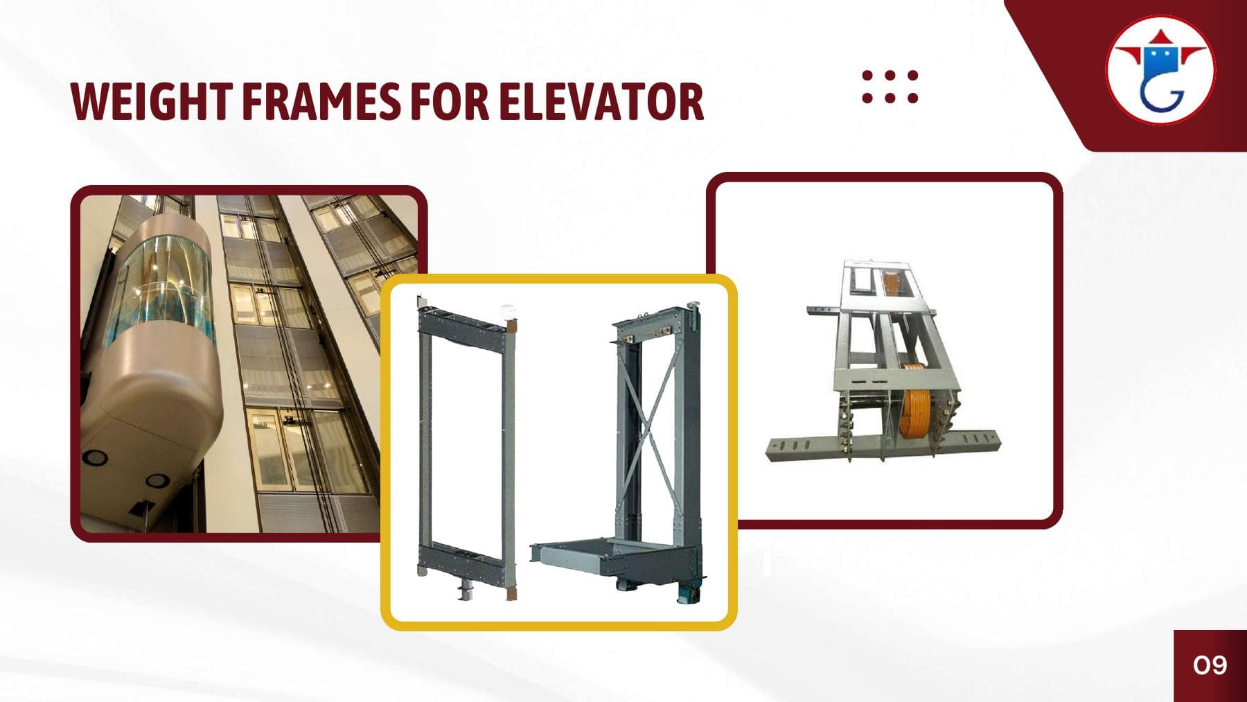
A frame section carries three jobs at once: it locates the car or counterweight, it takes the weld that ties it to the crosshead or the stile, and it presents a face that will be coated and seen. Each job wants a different datum, and the cut file has to serve all three.
Start with the assembly datum rather than the part outline. On a counterweight frame, the datum is usually the rail-clip hole pair on the stile; on a car frame, it is the sling bolt pattern on the crosshead or the safety-gear mount on the upright. Position every other feature from that pair, not from the outside profile. The outside profile can be trimmed by the laser with ±0.5 mm and still be right, while a clip pair referenced to that edge inherits any error twice.
Then decide where the part breaks. Frame stiles longer than the brake bed have to be spliced, and a splice is a weld that will pull. On the 4,450 mm bed, a 2,000 mm upright forms in one hit with room for the back gauge; a 5,000 mm stile does not. If the design needs full length, plan the joint at a point where the splice is in compression and can be backed by a doubler, not at the point of maximum bending moment.
The limits that decide whether the drawing is cuttable
| Parameter | Typical frame requirement | Ganesh limit or note |
|---|---|---|
| Material and thickness | 3–6 mm CRCA car frame; 2 mm door and sill brackets | 0.8–40 mm across custom parts; laser to 20 mm, iron worker 30–40 mm for plate |
| Cut profile tolerance | ±0.5 mm general | ±0.5 mm typical; tighter features by agreement at quotation |
| Hole-to-bend distance | ≥ 2.5 × t + inside radius | Rule applied at cut-file review; below it, hole is drilled after forming |
| Minimum hole diameter | ≥ 1.0 × thickness | Small features under 1 × t cut with taper; specify reamed if functional |
| Maximum part length | Fits brake bed for single-hit forming | 4,450 mm bed, 200 T, 5-axis, Delem control |
| Forming thickness | Up to 6 mm on frame stiles | 10 mm maximum on the press brake |
| Bend angle tolerance | ±1° on frame angles | Verified at first-off on both ends of long parts |
| Coating DFT | 60–80 µm polyester powder | Measured with DFT gauge; cross-hatch adhesion tested |
Counterweight frame and car frame are not the same cut file
The counterweight frame is a flat, repetitive part family. Stiles and crossbars are cut from 3–5 mm CRCA in nests that repeat every month, so the cut file stabilises and the fixture can be built once. The critical features are the rail-clip holes, the guide-shoe mounting faces and the rope-attachment bracket holes. Because the frame is largely planar, distortion comes from the weld, not the cut, and the welded counterweight frame article covers the shrinkage side in detail.
The car frame is a different problem. Uprights are usually channel or box sections formed from 2.5–4 mm sheet, with a large number of small features: door-operator mounts, cable-tray slots, safety-gear bolt holes and a top-of-car handrail pattern. Feature count drives laser time more than thickness does. A 2,400 mm upright with 40 holes and 12 slots costs more to cut than a 1,200 mm stile with six holes, even at twice the thickness.
Route the two families differently. Counterweight frames suit a fixed nest, a dedicated weld fixture and a batch of 50–200 before the fixture is checked. Car frames suit a revision-tolerant cut file and a reconfigurable fixture, because the door-operator pattern tends to change with the car interior. Mixing the two into one release plan is how a frame programme acquires a fixture that fits neither.
Where the laser stops and the brake starts
Laser cutting gives the frame its holes, slots, notches and profile in one setup, with no tooling charge and no blanking die to amortise. That matters most in the first year of a frame programme, when the door-operator pattern is still moving and a press tool would be obsolete before it paid back. The elevator components hub covers the rest of the frame and door work in this series, and the capability page confirms the material range: mild steel, CRCA, stainless, aluminium, brass and copper, so a stainless sill or an aluminium car-frame trim does not need a second supplier.
The brake is where the frame's geometry is decided. On the 200 T, 5-axis machine, a stile with four bends is formed in one programme with bend allowance calculated from the material grade and the measured thickness, not from the nominal. The Delem control stores the bend table per material, so repeat batches bend the same way after a coil change. Where the frame needs a bend within 25 mm of a cut edge, that edge should be deburred before forming — a laser-cut burr on the inside of a flange becomes a crack starter once the part is loaded.
Springback is the second source of drift. A 4 mm CRCA stile bent to 90° typically springs back 1–2°, which the control compensates by over-bending. If the material changes grade between releases and the bend table is not updated, the angle drifts by up to 1.5° and the frame's diagonal moves 5 mm over a 2,000 mm height. Freeze the material grade on the drawing and tell the supplier when it changes.
Welding a frame section without losing the cut geometry
Welding is where most frame geometry is lost. Manual MIG on a 3 mm stile pulls 1–2 mm per 100 mm of weld length unless the part is restrained, and a frame has long welds at the corners. The route that holds tolerance is fixture-first: locate the parts on the cut holes and the formed faces, clamp, weld in a balanced sequence from the centre outward, and release only after the frame has cooled.
Ganesh runs three CLOOS robotic MIG cells and more than 30 manual MIG/MAG, spot and SPM stations, with fixtures designed and built in the in-house tool room. For a counterweight frame, the robotic cell repeats the same weld sequence and the same heat input on every frame, which is what keeps diagonal variation inside a few millimetres across a batch. For a one-off car frame variant, manual welding on a checking fixture is the cheaper route, because the fixture cost is lower than programming and proving a robot cell for a single frame.
Two rules keep weld distortion out of the fit-up:
- Weld the frame before the final machining or reaming of any clip hole that must be precise.
- Leave the coating until after the frame is welded, straightened and checked — a 60–80 µm powder film will not hide a 3 mm twist, and stripping a coated frame to correct it costs more than the coating.
Coating and the inspection evidence that matters
A frame section is coated after welding, in the seven-tank pretreatment line and the electrostatic powder booth, at 60–80 µm dry film thickness on polyester powder. The checks that matter for a lift frame are adhesion, coverage on cut edges and coverage inside the weld throat. A frame that ships with a 40 µm film on a cut edge will show rust at that edge within the first wet season, and the complaint will arrive as a coating failure even though the cause was a cut-file decision.
Inspection should be built around the assembly, not the part. Record:
- Outside length and width of each frame member, measured on the formed part.
- Diagonal difference across the frame, measured after welding and before coating.
- Rail-clip and guide-shoe hole positions, referenced to the agreed datum.
- Bend angles at both ends of every long member, not only at the first end.
- DFT and adhesion result on one frame per batch, with the batch number on the record.
The diagonal is the single most useful number. A frame with a 4 mm diagonal difference over a 2,000 mm height will fight the guide rails during installation, and the fitter will blame the rails. Capturing it at first article and on every tenth frame catches the drift before dispatch rather than on site.
How Ganesh Multitech runs this route
Ganesh has manufactured sheet metal since 1992 across five units in Mumbai (Vasai) and Nagpur, with ISO 9001:2015 and ISO 14001:2015 certification, and supplies elevator frame and bracket work to TKE (thyssenkrupp Elevator) and Eros Elevators. The route for a frame section is the same one used for the elevator parts product range: 12 kW fibre laser on a 40 ft × 16 ft bed, deburr, form on the 200 T / 4,450 mm brake, fixture-weld on a CLOOS cell or a manual station, seven-tank pretreatment, powder coat, then first-article inspection with PPAP documentation available.
The 40 ft × 16 ft bed matters more for frames than it first appears. A nest that carries a full set of stiles for one car in a single sheet removes the sheet-to-sheet mismatch that shows up when stiles are cut from different coils on different days. For a 20-frame release, that is one laser programme, one nest and one measured thickness carried through the whole batch.
Where the frame needs a stainless or aluminium variant — a hospital car trim, a machine-room-less frame in a coastal building — the same route applies with material-specific cutting parameters, and the weld process changes from MIG on steel to the appropriate filler and cleaning routine. Say so on the drawing, because aluminium frame sections need a different fixture and a different post-weld finish.
What the lift drawing has to settle
- Assembly datum: the hole pair or face from which every other feature is dimensioned.
- Material grade and thickness, frozen, with the standard it is ordered to.
- Critical hole pattern with its own tolerance, separate from the general ±0.5 mm.
- Bend lines, inside radius and the bend allowance assumption, or a STEP file that carries them.
- Weld symbol and finish requirement: as-welded, dressed, or ground flush on visible faces.
- Coating system, colour, DFT range and any masked faces or threads.
- Quantity per release and per year, so the fixture and nest decision can be priced.
The RFQ checklist covers the fields a frame quotation needs in one pass; a drawing that answers all seven gets a comparable price from every supplier, and a frame that is quoted as a part rather than an assembly is usually the one that fails at installation.
When laser cutting is the wrong route for a frame
Laser cutting is not the right cut for a frame section when the annual volume is above roughly 5,000 identical stiles and the geometry is frozen. At that point a progressive die blanks and pierces the stile in one hit, and the piece price drops below the laser route by a margin that repays the tool. The crossover is a calculation, not an opinion, and it belongs in the same review as the fixture decision — the stamping versus laser cutting comparison walks through the arithmetic.
It is also the wrong route when the drawing asks for a hole position that cannot survive the bend and the part cannot be drilled afterwards because of access. In that case the design has to change, and the cheapest time to change it is before the tool or fixture is built.
Send the frame drawing with the revision, material, coating system and monthly quantity to start a review. The engineering team will return the cut-file comments, the bend sequence, the fixture assumption and a piece price with the tooling quoted separately.
Frequently asked questions
What thickness is an elevator frame section normally cut from?
Car frame uprights and counterweight stiles are usually 3 mm to 6 mm CRCA or structural-grade mild steel, with 2 mm on lighter landing-door and sill brackets. Ganesh cuts 0.8 mm to 20 mm on the 12 kW fibre laser and forms up to 10 mm on the 200 T brake, so the material choice does not constrain the route.
Can laser-cut holes be used for the guide-rail clip bolts?
Yes, provided the hole is not within 2.5 × thickness plus inside radius of a bend and the bolt pattern is toleranced as a group. For clip fixing at 8 mm and above, drill or ream after cutting if the drawing calls for H11.
How much does laser cutting add to the cost of a counterweight frame?
The cut itself is usually the smaller share once the frame is welded and coated. Cutting cost tracks thickness, perimeter length and nesting yield; a well-nested sheet of 4 mm CRCA cut on the 40 ft × 16 ft bed typically carries less laser time per frame than two separate jobs run a week apart.
Do you need a STEP file or a DXF?
Send both if you have them. The DXF is the cut file; the STEP carries the formed geometry and the bend lines. Ganesh accepts PDF, DXF, DWG and STEP, and a drawing that states revision, material and finish on the same sheet.
Sources
Have a frame drawing ready for review?
Send the current revision with material, thickness, bolt-pattern tolerances, finish and monthly quantity. Our engineering team reviews the cut file, bend sequence and weld fixture before quotation.
Send a drawing