Key takeaways
- Four ropes on a 1,000 kg car with 630 kg rated load carry about 4.0 kN each, so an 8 mm bracket sees roughly 31 MPa bearing stress: strength never governs the design.
- Cut the pin hole 2 mm undersize and ream to Ø16 H8 after welding, because four 5 mm fillets pull the bore 0.2–0.4 mm out of position on a 120 mm bracket.
- Keep rope-centre spacing within ±0.5 mm in the fixture and mask the bore before coating, or 70 µm of powder turns an H8 fit into an interference.
- A 5 mm fillet leg is 0.6t on 8 mm plate and gives about 19 MPa shear over 120 mm of weld, so specify continuity and a clean toe rather than a bigger leg.
- EN 81-20 needs a rope safety factor of at least 12 with three or more ropes; the bracket transfers that load, it does not create the factor.
Elevator rope attachment bracket manufacturing starts with a load number, and the number is not stress. On a 1,000 kg car with a 630 kg rated load, four ropes in 1:1 roping carry about 4.0 kN each at rest. Through an 8 mm side plate and a Ø16 pin, bearing stress is roughly 31 MPa. The plate yields above 250 MPa. Nothing about this bracket is a strength problem, which is why so many of them fail for reasons that never appear in a stress calculation: a bore that moved during welding, a weld toe with 0.5 mm of undercut, or powder in the pin bore.
The bracket has one job that matters to the installer: it must put the rope centres where the sheave and the hitch plate expect them, within a millimetre, after welding and after coating. That is a fixture and sequence problem, and it is decided before the first cut.
This page follows the route for an 8 mm bracket with two side plates, a Ø16 pin and four rope falls, including the load arithmetic, the reaming step that most drawings leave out, and the inspection that proves the bracket before it leaves.
How much load does one rope attachment bracket carry?
Start from the suspended mass. Car 1,000 kg plus rated load 630 kg is 1,630 kg, or 16.0 kN under gravity. Four ropes share it in 1:1 roping, so each rope carries 4.0 kN static and each bracket, if it terminates two ropes, carries 8.0 kN.
Dynamic factors raise that in service: acceleration, braking and the buffer case. EN 81-20 handles this through the rope safety factor rather than through a bracket stress check. With three or more ropes the total breaking load of the suspension must be at least 12 times the static load, so this installation needs 12 × 16.0 kN = 192 kN of aggregate breaking load. Four Ø10 mm 6×19 FC ropes at 1770 MPa, each with a minimum breaking load around 52 kN on its certificate, give about 208 kN, which clears the requirement by roughly 8%.
That arithmetic belongs to the lift designer. The bracket's part is to transfer 8.0 kN without moving, and to do it for the life of the installation without the rope bearing on a sharp edge or a coated bore.
Bracket dimensions and the limits we hold
The values below are for an 8 mm E250 bracket with two side plates and a Ø16 pin, welded in a fixture and powder coated. The third column is what we will commit to on a drawing.
| Feature | Typical drawing callout | Ganesh limit or note |
|---|---|---|
| Base and side plate | 8 mm IS 2062 E250 | 6–12 mm plate; laser cuts to 20 mm |
| Inside bend radius | R8 | R8 minimum at 1.0t; R10 preferred across the plate width |
| Pin bore | Ø16 H8 | Cut Ø14, ream to H8 after welding; ±0.05 mm on diameter |
| Bore perpendicularity | not usually stated | 0.1 mm over the 8 mm plate, checked with a pin in the fixture |
| Rope centres | 60 mm | ±0.5 mm between centres, ±0.3 mm from datum to first rope |
| Hole position after welding | ±0.2 mm | ±0.3 mm achievable as-welded; ream in fixture for ±0.1 mm |
| Fillet leg | 5 mm | 5 mm leg on 8 mm plate; continuous, ISO 5817 level C visual |
| Weld access | not usually stated | 15 mm clear for a 45° torch angle at a 5 mm leg |
| Bracket face flatness | 0.3 mm | 0.3 mm against the machine beam or hitch plate face |
| Coating | 70 µm polyester powder | 80 µm where the shaft is damp; bore and mating face masked |
| Static bearing stress | not usually stated | About 31 MPa per plate at 4.0 kN on a Ø16 pin |
| Bracket mass | not usually stated | 3.2 kg at this size; confirm before specifying a lifting point |
Elevator rope attachment bracket manufacturing: cutting and forming 8 mm plate
The blank is laser cut on the 12 kW fibre laser, which handles 8 mm mild steel comfortably and holds the profile within ±0.1 mm on the outside shape. The two side plates and the base can be cut as one development if the bracket is a folded U, or as three pieces if the side plates are set at an angle. The folded version removes two welds and is the better design where the geometry allows it.
At 8 mm the inside radius should be R8. A tighter radius on plate this thick concentrates strain on the outside skin and can open a crack at the bend line during forming, particularly if the plate is sheared rather than laser cut, because a sheared edge already carries micro-cracks. Forming is done on the 200 T, 5-axis brake with the 4,450 mm bed, which is rated to 10 mm and has the tonnage per metre for an 8 mm air bend at a 64 mm V die.
Springback at 8 mm is not small. At R8 the material returns about 1.5–2.5° after the ram lifts, so the brake programme overbends, and the first article is checked on an angle gauge rather than against the tooling. If the bracket has two bends that set the rope centres, form both in the same set-up; re-clamping between bends is where 0.5 mm of centre error enters.
The pin bore is cut at Ø14, not Ø16. That 2 mm allowance is the whole point of the next section.
Why the pin bore is reamed after welding
A welded bracket moves. The base-to-side-plate fillets cool and shrink, the two side plates pull towards each other, and the bore that was round in the flat becomes oval and slightly smaller. On an 8 mm bracket with 5 mm fillets the movement is typically 0.2–0.4 mm, which is four to eight times the H8 tolerance band on a Ø16 bore.
There are two ways to deal with it and only one is reliable:
- Drill and ream after welding, in the fixture. The bracket stays clamped on its datum faces and rope-centre pins, the bore is opened from Ø14 to Ø16 H8 with a drill and a hand reamer or a boring head, and the centres are proven by the fixture rather than by the operator.
- Cut to size and hope. It works on a bracket with small fillets and one side plate. It fails as soon as the design has two side plates and a continuous weld, which is most of them.
We use the first route. It adds one operation and about 90 seconds per bracket, and it removes the most common warranty argument in this part family: a pin that will not go in, or goes in with a hammer and then will not come out after a year in a damp shaft.
The bore is also the feature that coating destroys. Powder at 70 µm on the bore wall takes 0.14 mm off the diameter, which is more than the entire H8 band, so the bore is plugged before the booth and the plug line is touched in with a repair coat afterwards.
Welding so the bracket stays where the fixture put it
The weld plan is short: two side plates to the base, a gusset if the drawing has one, and a hitch plate where the ropes terminate. Total weld length is usually 100–150 mm, mostly 5 mm fillets.
A 5 mm leg on 8 mm plate is 0.6t, which is enough for the load and small enough to keep heat input down. Over 120 mm of weld at a 3.5 mm throat, the shear area is 420 mm² and the stress at 8.0 kN, the load on a two-rope bracket, is about 19 MPa. The weld is not sized by stress; it is sized by the rule that a fillet on plate should not be smaller than about half the plate thickness, and by the need for a continuous toe that will not start a fatigue crack.
Sequence rules that keep the centres:
- Locate on the bore and the rope-centre pins, not on the outside profile. The outside profile carries the laser tolerance; the pins carry the installation tolerance.
- Weld opposite sides in pairs. One side plate welded fully before the other pulls the bracket into a parallelogram.
- Clamp until below 50 °C. Releasing a warm bracket lets the last welds shrink against free material.
- Keep the torch off the mating face. A 0.5 mm spatter bump under the machine beam is a bracket that rocks and a rope that runs off centre.
Weld access is a drawing decision. A gusset placed 8 mm from the side plate leaves no room for a 45° torch at a 5 mm leg, and the welder will either bridge the gap or skip the weld. Fifteen millimetres of clear access is the number to design to. The welded assembly tolerances guide covers how much distortion a fixture can absorb before the tolerance has to change.
Coating a bracket that has to stay conductive and fit
The coating on a rope bracket is a corrosion barrier with three exceptions that must stay bare: the pin bore, the mating face against the machine beam or hitch plate, and any earthing point the OEM has specified.
Everything else takes 70 µm of polyester over seven-tank pretreatment. In a damp shaft, which is most shafts below ground level, 80 µm is the better call, and the pretreatment matters more than the extra 10 µm because a phosphate layer of 2 g/m² is what stops corrosion creeping from a scratch. A neutral salt spray comparison to ISO 9227 on a coupon is the evidence a lift OEM usually asks for, and it is a coupon test, not a part test.
Masking is specified on the drawing, not left to the coater:
- Pin bore, plugged, with the plug line repaired after cure.
- Mating face, taped, so the bracket sits flat rather than on a compressible film.
- Threaded holes, plugged, because an M8 thread with 70 µm on the flanks will not take a bolt.
- Rope contact faces, bare, because rope bearing on cured powder is rope bearing on a soft layer that will wear and fret.
The elevator parts range runs this coating route on counterweight frames, car frames, guide rail brackets and door hardware, so the masking schedule is a standard document per part family rather than a note added at quotation.
Inspection before dispatch
Five checks, in this order:
- Pin gauge through both side plates. A Ø16 gauge pin at the specified centres, engaged with the bracket clamped on its datum. This proves the bore and the centres in one action.
- Rope-centre spacing, measured between pin centres or with a setting gauge, against ±0.5 mm.
- Weld visual to ISO 5817 level C, with undercut, porosity and toe condition recorded. The toe is the fatigue feature, so it is checked rather than glanced at.
- Coating: dry film thickness at five points per face with a magnetic gauge, and a cross-hatch adhesion test to ISO 2409 on the first part of each batch.
- Masking audit, looking at the bore, the mating face and every thread, before the part is packed.
First article inspection adds the bore perpendicularity, the flatness of the mating face and the mass. PPAP documentation and dimensional reports are available where the lift OEM's quality system requires them. What we do not do is proof-load the bracket or issue a rope safety factor: that is the OEM's design responsibility under EN 81-20, and pretending otherwise would put a number on our paperwork that we cannot support.
The Ganesh route for lift brackets and frames
Brackets are cut on the 12 kW fibre laser with the 40 ft × 16 ft bed, formed on the 200 T, 5-axis brake, and welded in fixtures on the three CLOOS cells or at the manual stations, depending on volume. The bore is reamed in the same fixture, the part is blasted where the drawing requires it, pretreated on the seven-tank line and powder coated in the 18 ft × 14 ft booth. Counterweight frames, car frames and slings for TKE and Eros Elevators run on the same route, which is why the fixture design and the reaming step are already in place for a new bracket.
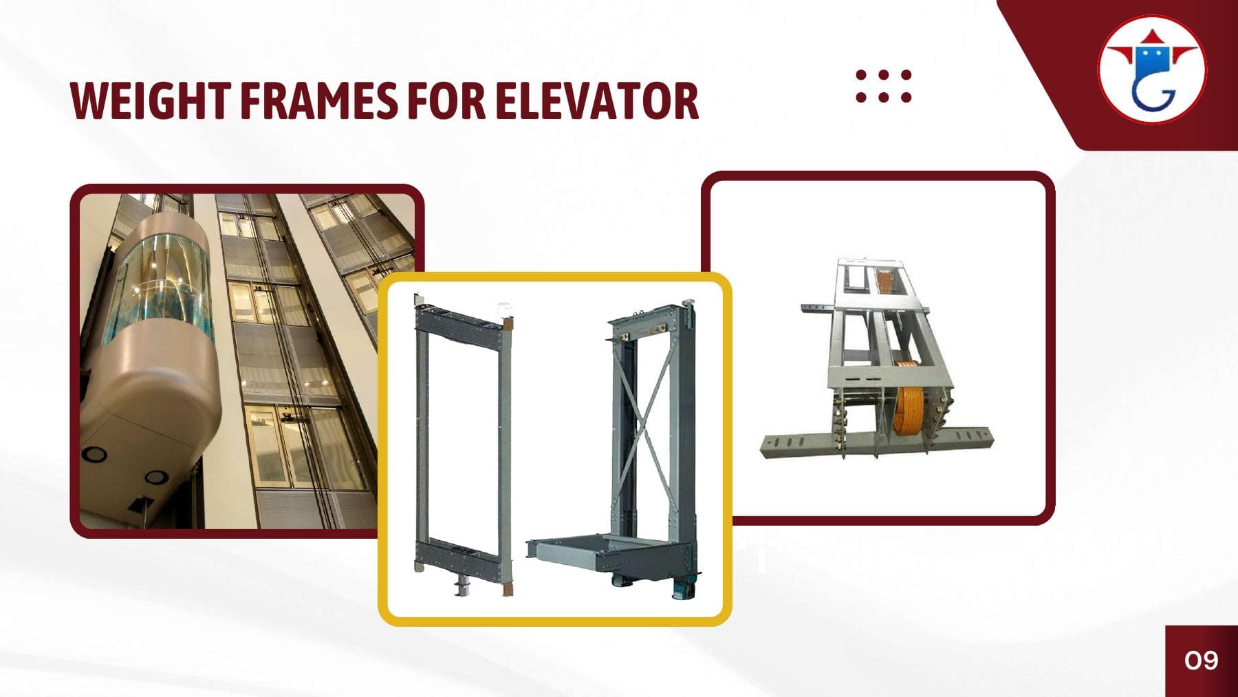
The bracket family sits under the elevator and lift components hub, and the frame-level tolerances that the bracket has to fit into are set out in the car frame manufacturing route. Where the bracket bolts to a counterweight frame, the welded counterweight frame guide covers the mating face and the coating allowance at the joint.
What to put on the bracket drawing
- Rope load per bracket and the number of falls, with the rope diameter, so the weld and plate size can be checked rather than guessed.
- Rope centres and the datum they are measured from, with the tolerance.
- Pin diameter and fit, stated as Ø16 H8, plus the pin material or the OEM standard it comes from.
- Plate grade and thickness, with the IS 2062 grade named.
- Weld map: leg size, length, continuity and ISO 5817 level, with the cosmetic welds marked separately.
- Post-weld machining: the bore and any face that must be flat after welding.
- Coating system and masking schedule, with DFT and the faces that stay bare.
- Inspection and evidence: pin gauge, dimensional report, first article, PPAP.
The RFQ checklist lists the rest of the fields that change a quotation, including annual volume and the release pattern, and it takes less time to fill than a second quotation round.
When a fabricated bracket is the wrong route
Fabrication is wrong when the bracket is a high-volume standard part with a forged or cast shape that carries the rope termination in one piece. A forging has no weld toe to fatigue and no bore to ream, and above a few thousand identical pieces the tooling is usually justified.
It is also the wrong route where the drawing calls for a machined clevis with a tolerance band tighter than ±0.05 mm on centre distance. We ream and inspect to that on a bracket, but we are not a machining shop, and a part that is fundamentally a machined component should be quoted as one.
Hot-dip galvanising is not part of our line. A galvanised bracket needs the bore reamed after dipping, because the zinc layer changes the fit exactly as powder does, and the route then has an external process in the middle of it. Where a shaft is wet enough to need zinc rather than powder, that conversation belongs at the drawing stage rather than after the first lot.
Send the current revision with the rope load and the pin detail through the RFQ route, and the fixture, the reaming step and the masking plan come back with the price rather than after the first article.
Frequently asked questions
What material is an elevator rope attachment bracket made from?
8 mm IS 2062 E250 plate is the common choice for a traction lift bracket, with 6 mm used below about 10 kN per bracket and 10–12 mm where the bracket also carries the machine beam connection. The plate is chosen for stiffness, weldability and thread depth rather than for static strength.
Why must the pin hole be reamed after welding?
Because welding shrinks. Four 5 mm fillets around an 8 mm bracket close the pin bore by 0.2–0.4 mm and pull it off position, so a hole cut to Ø16 H8 in the flat will not accept a Ø16 pin after the fixture releases. Cut Ø14, weld, then ream to H8 in the same fixture that set the rope centres.
How tight should the rope centres be?
±0.5 mm between rope centres, and ±0.3 mm from the bracket datum to the first rope. Rope misalignment shows up as sheave groove wear and rope rubbing, and it cannot be corrected at installation without shimming the machine beam.
Can the bracket be powder coated over the pin bore?
No. Powder at 70 µm on the bore wall reduces a Ø16 H8 bore by 0.14 mm on diameter, which is more than the whole H8 tolerance band. Mask the bore and the mating face, then touch in the mask line with a matching repair coat.
Does Ganesh proof-load rope attachment brackets?
No. We fabricate to the drawing and inspect dimensions, weld quality and coating, but the proof load and the rope safety factor are the lift OEM's design responsibility under EN 81-20. A project that needs a tested bracket should have that test run by the OEM or a test house.
Sources and further reading
- EN 81-20 — Safety rules for the construction and installation of lifts, including suspension rope factors and clearances · reviewed 3 Nov 2026
- IS 2062 — Hot rolled medium and high tensile structural steel, the plate grades and impact requirements behind an E250 bracket · reviewed 3 Nov 2026
- ISO 5817 — Quality levels for imperfections in fusion-welded steel joints, the visual acceptance level for the fillets · reviewed 3 Nov 2026
- ISO 2768-1 — General tolerances for linear and angular dimensions where the drawing carries no individual tolerance · reviewed 3 Nov 2026
Have a rope bracket drawing ready?
Send the current revision with the rope load, rope diameter and centres, pin size, weld class and coating system. Our engineering team reviews the fixture and the reaming sequence before quotation.
Send a drawing