Key takeaways
- Set the fixture datum on the guide shoe mounting faces and the safety gear bolt holes, not on the outside of the stiles, because those are the two interfaces the shaft cares about.
- Hold the sling diagonal within ±2 mm and stile verticality within 1 mm per metre; a 2.4 m stile that leans 1 mm/m puts the crosshead 2.4 mm off, and the guide shoes take the difference.
- Weld the two stiles in a balanced, alternating sequence and leave the crosshead to last: a crosshead welded hot on one side bows the sling and moves the rope hitch.
- Mask the guide shoe and safety gear faces before powder coating; a 160 µm film there closes the shoe clearance the OEM designed for.
- Inspect diagonal, verticality and pad flatness before and after the oven cycle, because powder cure at 180–200 °C releases the stress the fixture was holding.
Elevator car frame manufacturing is decided by three numbers that most drawings leave out: plan diagonal, stile verticality and the position of one guide shoe face to the other. Miss them and the sling arrives at site, the fitter shims, and the car develops a rub that the service team chases for a year.
This is the manufacturing route for a welded car frame at Ganesh, the fixture decisions that hold those three dimensions, and the point where a fabricated sling stops being the right answer. Both TKE and Eros Elevators take lift components from us; the component range and its product route sit in elevator sheet metal parts and the elevator and lift hub.
Why does 1 mm per metre matter on a lift sling?
A sling 2.4 m tall that leans 1 mm per metre puts the crosshead 2.4 mm off plumb. The guide shoe clearance — commonly 2–3 mm per side on a sliding guide — absorbs that error on one side and loses it on the other. The symptoms are a rub that changes with car load and a rumble at each rail joint.
The three dimensions interact. Diagonal error rotates the plan, verticality error tilts it, and guide shoe face coplanarity sets how the shoe sits on the rail. Get all three right and the installer has adjustment left. Get two right and the third consumes the whole adjustment range, which is what turns a routine installation into a two-day site visit.
The shaft is unforgiving because it has no adjustment on the rail side. Lift guide rails are set to their own tolerance during installation, and the car has to follow them. Every millimetre of sling error is a millimetre the fitter has to remove somewhere else.
What are the parts of an elevator car frame?
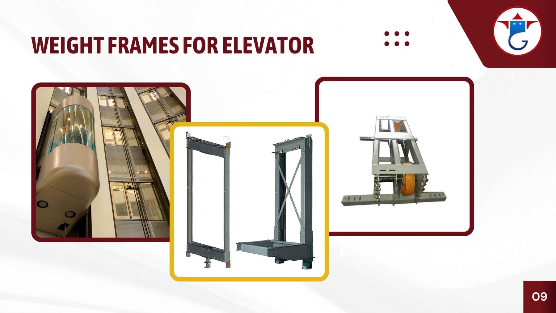
The sling is a portal frame. Two vertical stiles carry the load from the crosshead down to the lower beam, the lower beam carries the platform and the car floor, and the crosshead picks up the rope hitch or the sheave assembly. Bolted or welded to that structure are the guide shoe brackets, the safety gear mounting plates, the governor tension fixing and the platform brackets.
Each of those attachments has a different tolerance requirement, and the drawing should treat them differently. The guide shoe brackets and the safety gear plates are functional interfaces: they position the car against the rail and stop it if a rope fails. The platform brackets and cladding fixings are cosmetic and structural but not positional, and holding them at ±0.2 mm adds cost without adding value.
Material choice follows the same logic. Stiles and crosshead on a mid-rise sling are usually 6–10 mm plate or a formed channel in IS 2062 grade steel; platform brackets and covers are 3–4 mm pressings in CRCA. Mixing the two in one drawing is normal, but each should carry its own thickness note, because a fabricator who has to guess will pick the heavier one and quote accordingly.
Where the fixture datum goes
Fixtures make or break a car frame. The datum should be the two interfaces that the shaft sees: the guide shoe mounting faces and the safety gear bolt holes. Locate on those, and every other dimension follows from the surfaces that matter.
The common mistake is to fixture on the outside of the stiles because that is the largest, flattest surface available. It is also the surface with the widest tolerance, since plate thickness varies and the outside face carries the weld. A sling built that way can be square to its own outside faces and still put the guide shoes 1.5 mm out of position relative to each other.
The second fixture decision is whether the frame is welded upright or laid flat. Upright welding keeps gravity working with the frame, which helps on tall slings, but it makes the crosshead weld overhead and harder to control. Flat welding gives better access and a more consistent bead, at the cost of needing a fixture stiff enough to hold the plan square while the frame is on its side. For slings above 3 m we build the fixture to suit the geometry rather than forcing one orientation.
The dimensions that decide whether the car installs
The table below is the tolerance set we work to on a welded sling. Values in the first two columns are common lift-industry practice; the third is what the fixture and inspection at Ganesh hold.
| Feature | Typical value | Ganesh limit or note |
|---|---|---|
| Stiles and crosshead material | 6–10 mm plate or formed channel, IS 2062 | Plate cut on the 12 kW fibre laser, 40 ft × 16 ft bed |
| Stile verticality | 1 mm per metre | Checked with a plumb or a laser against the fixture datum |
| Plan diagonal | ±2 mm | Measured corner to corner before and after coating |
| Crosshead to lower beam | ±1.5 mm | Set in the fixture, not adjusted after welding |
| Guide shoe face flatness | 0.3 mm over the pad | Machining is not offered; pads are formed flat and masked |
| Guide shoe face coplanarity across the sling | 1 mm | Measured on the two shoe planes in one setup |
| Safety gear hole position | ±0.5 mm | Laser cut in the same nest as the plate outline |
| Rope hitch position | ±2 mm | From the crosshead centreline, not from a stile face |
| Platform bracket position | ±1.5 mm | Looser than the functional interfaces by design |
| Weld fillet leg | 4–6 mm on 6–8 mm plate | Set on the fixture drawing; sequence numbered |
| Powder coating build | 70–90 µm | DFT gauge on stiles; guide shoe and gear faces masked |
| Squareness after oven cycle | ±1 mm additional movement | Re-checked after cure, recorded on the inspection sheet |
Two rows in that table are worth arguing about before the order, not after. The guide shoe face flatness of 0.3 mm is achievable on formed plate but not on a face that has been welded on the reverse side without support. If the OEM needs better, the pad has to be a separate machined plate bolted on, because we do not machine welded slings.
The diagonal row is the one installers feel. A ±2 mm diagonal on a 1.6 m × 2.4 m sling is roughly a 0.05° error, and it is well inside what a guide shoe can absorb. A ±5 mm diagonal is not, and it usually arrives with a matching stile lean.
How the frame is welded without losing the diagonal
Weld sequence, not weld size, controls the diagonal. Three rules do most of the work.
Weld symmetrically about the centreline. Run a bead on the left stile, then the equivalent bead on the right, then return. If the left stile takes its full run first, the frame pulls left and stays there; the right stile then fights it and the diagonal ends up wherever the two effects land.
Weld the crosshead last and in short passes. The crosshead has the longest continuous joint in the frame and the most influence over the stiles. Long single passes bow it, and a bowed crosshead moves the rope hitch and tilts the safety gear plane.
Leave the functional pads until the frame is square. Fit and weld the guide shoe pads after the structural welds have cooled and the diagonal has been checked, in a secondary fixture that holds the pad plane. This is the single biggest difference between a sling that installs and one that is adjusted on site.
Distortion after welding is where most rework originates. We do not flame straighten a structural sling. If the diagonal is out before coating, the frame goes back into the fixture, the offending joint is cut and re-welded, and the frame is re-measured. After coating, a frame that has moved is re-made, because straightening heat on a coated structural part destroys the finish and the record.
Coating: where the mask goes
A car frame is normally powder coated, and the coating schedule matters as much as the weld. Masking is decided by function, not by appearance: guide shoe mounting faces, safety gear bolt holes, rope hitch faces and any earth bonding point stay bare. Everything else is coated, including the inside of the stiles, because shaft environments are damp and bare steel blooms quickly.
Powder is applied after seven-tank pretreatment and, where the drawing calls for it, shot blasting. Caveats in the frame go through the 16 ft × 16 ft blast chamber, the frame is pretreated on the seven-tank line, coated in the 18 ft × 14 ft electrostatic booth and cured in the oven. DFT and adhesion are checked with a gauge and a cross-hatch test.
Two coating details cause site problems. The first is film build on a masked edge: masking tape leaves a hard step where the film ends, and a guide shoe sitting across that step rocks. Feather the mask line or mask a land wider than the shoe. The second is the oven cycle itself: cure at 180–200 °C relaxes residual stress, so a sling that measured 1 mm of diagonal before coating can move 1 mm more. Measure after cure, and record both figures.
Elevator car frame manufacturing: where the cost sits
Four things drive the price of a sling, and only one of them is steel. Plate weight is the visible cost. Fixture cost is the one that surprises buyers, because a sling fixture with location on the shoe faces and the gear holes is a fabricated tool in its own right, and it is quoted once and amortised across the order. Weld length is the third: a frame with 12 m of fillet weld takes roughly three times the arc time of one with 4 m, and the difference shows in both labour and distortion control. Masking is the fourth, and it is almost always underestimated, because every masked face is hand work before and after the booth.
The cheapest way to reduce cost without touching the design is to reduce the number of distinct slings in a programme. Three car sizes that share a stile section, a crosshead and a shoe bracket can often be built on one fixture with different stop positions, which spreads the tooling and keeps the inspection routine identical across the range.
What changes between frame one and frame forty
A sling that is right on the first article and wrong on the fortieth is a fixture problem, not a welding problem. Location pins wear, clamps lose preload, and a fixture that was set with a 0.05 mm feeler gauge drifts as the pins take load. Replaceable pins and a scheduled fixture check every few hundred parts keep the diagonal inside ±2 mm across a batch.
Plate batch variation is the second source. Thickness tolerance on hot-rolled plate means a 6 mm nominal can arrive at 5.7 mm, and a fixture that locates on the outside face will place the shoe face differently on that plate. Locating on the functional faces removes most of this sensitivity, which is another reason the datum choice matters more than the fixture's stiffness.
Weld parameters are the third. A robot cell holds current, wire feed and travel speed, so the heat input is repeatable; a manual station depends on the welder. Where a sling is split between the two, the manual joints should be the ones furthest from the functional faces.
What Ganesh runs for car frames
Car frames at Ganesh start as laser-cut plate on the 12 kW fibre laser, whose 40 ft × 16 ft bed lets a crosshead and both stile blanks come off the same nest, which keeps hole patterns consistent between frames of a batch. Formed parts run on the 200 T, 5-axis CNC press brake with a 4,450 mm bed and Delem control, so the bend programme for a stile is stored against the part number rather than rebuilt each time.
Welding happens in fixtures designed and built in our own tool room, on one of three CLOOS robotic MIG cells for repeat slings, or at the manual MIG stations where the joint access suits a person better than a torch on a robot. Fixtures are maintained for the life of the part, with replaceable location pins, because a worn pin is a diagonal error that appears halfway through a batch.
The routes for the neighbouring components are described in welded elevator counterweight frames and laser-cut elevator frame sections; the counterweight side of the same shaft is covered in the counterweight frame article. The broader welded assembly capability is under welded assemblies.
What the lift drawing has to settle
- The three functional interfaces, dimensioned from one datum: guide shoe faces, safety gear holes and rope hitch.
- Plan diagonal and stile verticality, as tolerances rather than notes.
- Plate thickness per member, with the material grade.
- Weld symbols with a sequence number, and the joints that must not be welded after the frame is square.
- Masking schedule, face by face.
- Finish specification: pretreatment, powder type, colour, DFT range.
- Lifting and packing: sling above 2.5 m travels braced, and the brace points belong on the drawing.
- Documentation: first article report, PPAP if the OEM asks, mill certificate traceability.
The RFQ checklist turns these into a form that can be sent with the drawing, so the first quotation does not come back with a list of questions.
When a welded sling is not the right answer
Welding is wrong when the shaft access cannot take a one-piece frame, when the OEM's strength calculation assumes a bolted and adjustable sling, or when the quantity is one prototype for a shaft that is still being surveyed. In each case a bolted or knock-down frame is easier to adapt, at the cost of joints that can move after installation.
We do not machine guide shoe pads after welding, do not perform the structural strength calculation that the lift standard requires, and do not flame straighten coated structural frames. Those three limits are worth knowing before the drawing is frozen: a sling designed around a machined pad is a different part from a sling designed around a formed one, and the price gap is larger than the tolerance gap suggests.
Frequently asked questions
What tolerance should an elevator car frame carry?
±2 mm on the plan diagonal, 1 mm per metre on stile verticality and ±0.5 mm on guide shoe and safety gear hole positions. Dimensions that only locate cladding can sit at ±1.5 mm.
Is the car frame welded or bolted?
Most low and mid-rise slings are welded in a fixture and delivered as one piece. Bolted slings suit sites with no crane access to the shaft, but every bolted joint is a place where the diagonal can move after installation.
How thick is an elevator car frame?
Stiles and crosshead are commonly 6–10 mm plate or formed channel, with 3–4 mm pressings for platform brackets and covers. Plate above 10 mm is cut but not formed on our 200 T brake.
Can a car frame be reworked if the diagonal is out?
Only within a small window. We re-fixture and re-weld a joint if the error is caught before coating. After the oven cycle we scrap or re-make rather than flame straighten a structural sling.
Do you supply lift slings with inspection documentation?
First article inspection reports are standard and PPAP is available where the lift OEM requires it. Material is traceable to mill certificates for structural sections and plate.
Sources and further reading
- IS 14665 — Electric traction lifts (Indian lift standard, outline dimensions and safety) · reviewed 3 Nov 2026
- EN 81-20 and EN 81-50 — Safety rules for the construction and installation of lifts · reviewed 3 Nov 2026
- ISO 2768-1 — General tolerances for linear and angular dimensions · reviewed 3 Nov 2026
Have a sling drawing ready for review?
Send the frame drawing, car rated load and shaft interface dimensions. We will review the fixture datum and the weld sequence before quotation.
Request a quote