Key takeaways
- Hold panel flatness to 1.5 mm over 2,000 mm and squareness to ±1.0 mm on the diagonal; a 2 mm bow shows as a wave in the reflection under a lobby light.
- Use 1.2 mm skin with 40 mm folded returns for doors up to 1,100 mm wide, and add a stiffener or go double skin above that.
- Allow 0.14 mm of coating build across a door gap; at 70 µm per face it eats a third of a ±0.5 mm gap tolerance.
- Keep the clear distance between car and landing doors within the 120 mm limit in ISO 8100-1; the panel route cannot fix a shaft that is out.
A landing door panel is the largest flat painted surface in a lift installation and the one a passenger stands closest to. Elevator landing door panel manufacturing is mostly a fight against 1–2 mm of bow in a 1.2 mm skin, because that bow shows as a wave under a lobby downlight, and the same panel sounds hollow every time the door closes.
Both problems come from the same place: a 1.2 mm skin with insufficient edge stiffness. A 900 × 2,000 mm door panel has 1.8 m² of unsupported sheet, weighing about 17 kg in 1.2 mm CRCA. Fold 40 mm returns on four sides and the panel becomes a shallow tray with a stiffness several times higher than the flat sheet. Skip the returns, or shorten them to 20 mm to save material, and the tray behaves like a drum.
Elevator landing door panel manufacturing is a flatness and stiffness problem wrapped in a clearance problem. This is the route we run for lift OEM programmes, the numbers we hold, and the drawing decisions that keep a door running quietly for a decade.
Why does a landing door panel bow?
It bows because the coating, the welding and the forming each add a little stress, and a thin panel has nowhere to put it. Three sources dominate.
The first is the fold itself. A 40 mm return on 1.2 mm CRCA at R1.2 puts the outer fibre near its limit, and the return pulls the panel into a slight dish along that edge. Two opposing returns balance each other; a panel with returns on the long edges only will bow across the width.
The second is welding. Hanger bracket reinforcements and stiffeners are spot welded or MIG welded to the back face, and each weld shrinks as it cools. A row of plug welds along the top edge pulls the top of the panel back by 0.5–1.0 mm, which is exactly where the eye goes first.
The third is coating. Powder cures at 180–200 °C, and the film shrinks on cooling. On a single-skin panel the film on the front face is under tension and the film on the back face is under the same tension, so the two roughly cancel. On a panel coated on one face only, the film pulls the panel into a dish of 1–2 mm over 2,000 mm.
The fix for all three is the same: stiffen the edge, balance the operations, and check flatness after coating rather than before.
Panel geometry, gaps and tolerances
The table is the landing door specification we work to. The middle column is what the drawing should state; the right-hand column is what we hold and where a request needs a conversation.
| Parameter | What the drawing should state | Ganesh practice or limit | Why it matters |
|---|---|---|---|
| Panel height | 2,000–2,100 mm clear, to the OEM drawing | 2,000 mm and 2,100 mm standard | Standard car and landing heights |
| Panel width | 700–1,200 mm per leaf | 700–1,100 mm single skin; 1,200 mm with stiffener | Width drives drumming and flatness |
| Skin thickness | 1.2 mm CRCA to IS 513, or 1.5 mm 304 | 1.2 mm CRCA; 1.2–1.5 mm stainless | Thicker skin adds mass, not stiffness |
| Return depth | 40 mm on all four sides | 40 mm standard; 30 mm minimum | Returns are the panel's stiffness |
| Inside bend radius | 1.0 t minimum | R1.2 at 1.2 mm | Tighter radius marks the face |
| Flatness | 1.5 mm over 2,000 mm, lobby face | 1.0–1.5 mm single skin; 1.0 mm double skin | Visible under grazing light |
| Squareness | ±1.0 mm on the diagonal | ±1.0 mm checked on a gauge table | A skewed panel rubs at one corner |
| Door gap | 4–6 mm at the leading edge | Set after coating; 0.14 mm coating build allowed | A 4 mm max gap closes after paint |
| Sill clearance | 3–5 mm to the finished floor | Set by the OEM's sill and guide shoe | Too low, the door scrapes; too high, it rattles |
| Hanger hole position | ±0.5 mm from the panel datum | ±0.5 mm laser cut; slotted ±2 mm where specified | Hanger adjustment is finite |
| Stiffener | Specify position and fixing method | 1.2 mm hat section, spot welded at 50 mm pitch | Stiffener weld pulls the face |
| Coating | Polyester powder 60–80 µm both faces | 60–80 µm, seven-tank pretreatment | Adhesion checked to ISO 2409 |
| Panel mass | State the maximum for the hanger | 17–24 kg typical for 900 × 2,000 mm | Hanger and roller rating |
The gap and sill rows are the ones that come back as site complaints. A door that rubs is usually not a panel problem at all. It is a panel that was flat when it left us, bolted to a hanger that was set 2 mm out, in a shaft where the landing sill was poured 3 mm high.
Single skin with returns, or double skin?
Up to about 1,100 mm wide, a single 1.2 mm skin with 40 mm returns on four sides is the economical choice and holds 1.0–1.5 mm flatness. The returns do the work: a 40 mm return raises the panel's edge stiffness by roughly an order of magnitude compared with a bare sheet, which is why the return depth matters more than the skin thickness.
Above 1,100 mm, or where the lobby lighting is grazing and the client is particular, a double-skin panel is the better answer. Two skins spot welded through a perimeter return and a mid-height stiffener give a flat face, a heavier feel and a much quieter close. The cost is a second skin, a second set of spot welds and roughly double the mass on the hanger.
The decision rule: single skin to 1,100 mm in a normal lobby, double skin above 1,100 mm or wherever the specification calls for a "flush, non-drumming" panel. A single skin at 1,400 mm will drum at every close, and no amount of stiffener welded to the back removes the sound without also showing a weld mark on the front.
The route: blank, form, weld, coat, hang
Cutting the skin and reinforcements
The 12 kW fibre laser on the 40 ft × 16 ft bed cuts 1.2 mm CRCA skins, hanger reinforcement plates and hat stiffeners in one nest. Laser cutting gives a square, burr-free edge that folds predictably; a sheared edge on 1.2 mm can leave a 0.1 mm burr that shows as a line through the paint after forming.
Skins are cut with the grain direction marked, because 1.2 mm CRCA bends differently across and along the rolling direction. The difference is small at R1.2 but it shows up as a 0.5 mm bow difference between two panels from the same sheet if one is nested across the grain.
Forming the tray
The 200 T, 5-axis brake with the 4,450 mm bed folds all four returns in four strokes, with the long edges first and the short edges second so the corners close cleanly. Corner relief is cut into the blank; without it, the second fold pulls the first return out of square by 1–2 mm.
Flatness is set here. A worn punch with a 0.2 mm radius difference along its length puts a wave into the fold line, and that wave reflects across the whole face of the panel. Punches are checked before a door run, not after, and the long-panel bending guide explains why the effect grows with panel width.
Welding the hanger reinforcement
Hanger plates and stiffeners are spot welded on the manual spot stations or on a CLOOS cell with a dedicated fixture. Spot welding is preferred over MIG on a visible panel because it puts less heat into the face; a MIG tack on the back of a 1.2 mm skin shows as a blue-grey spot on the front after painting.
The sequence runs from the centre outward on both sides, alternating, so the shrinkage balances. Welding one side of the hanger plate to completion first pulls the top edge back, and the panel then needs a mechanical straighten that stresses the weld it just made.
Coating and assembly
Panels pass the seven-tank pretreatment line and are powder coated at 60–80 µm on both faces, with the hanger holes and earth points masked. Adhesion is checked by cross-hatch to ISO 2409 on the first article, and DFT is checked on the face and inside a return.
Assembly is a trial fit on a frame: hanger brackets, rollers and the guide shoe are fitted, the door is hung, and the gap at the leading edge and the clearance at the sill are measured. A sample door from each batch is run through the opening cycle on the frame before packing.
The clearance stack that decides whether a door rubs
Four numbers stack at the bottom of a landing door: sill flatness, guide shoe clearance, panel squareness and hanger adjustment.
Take a panel with ±1.0 mm squareness, a sill poured ±2 mm, and a guide shoe with 2 mm of lateral clearance. The door can sit 5 mm off nominal at the leading edge before anything is adjusted. The hanger gives ±3 mm of vertical and ±2 mm of lateral adjustment, which covers it, but only if the hanger slots were cut at ±0.5 mm and not at ±1.5 mm.
Coating makes it worse in a way that is easy to forget. Powder at 70 µm on the panel edge and 70 µm on the door frame closes a nominal 4 mm gap to 3.86 mm. If the drawing says "4 mm maximum", the coated door fails inspection before it is hung. Specify 4–6 mm with the coating build called out, and the gap survives the paint line.
The car-to-landing door clearance is a separate and non-negotiable number. ISO 8100-1, which carries the safety rules for lift construction and installation, limits the clear distance between the car door and the landing door to 120 mm. That is a shaft and alignment requirement, not a panel tolerance, and a panel supplier cannot close a gap that the installation opened.
What Ganesh runs for landing doors
Landing door skins, hanger reinforcements and stiffeners are laser cut on the 12 kW fibre laser, formed on the 200 T, 5-axis brake with the 4,450 mm bed to 10 mm capacity, spot welded on the manual stations or a CLOOS cell with an in-house fixture, and coated on the seven-tank line in the 18 ft × 14 ft powder booth. Typical sheet metal tolerance is ±0.5 mm, tighter on critical features by agreement, and first article inspection and PPAP are available.
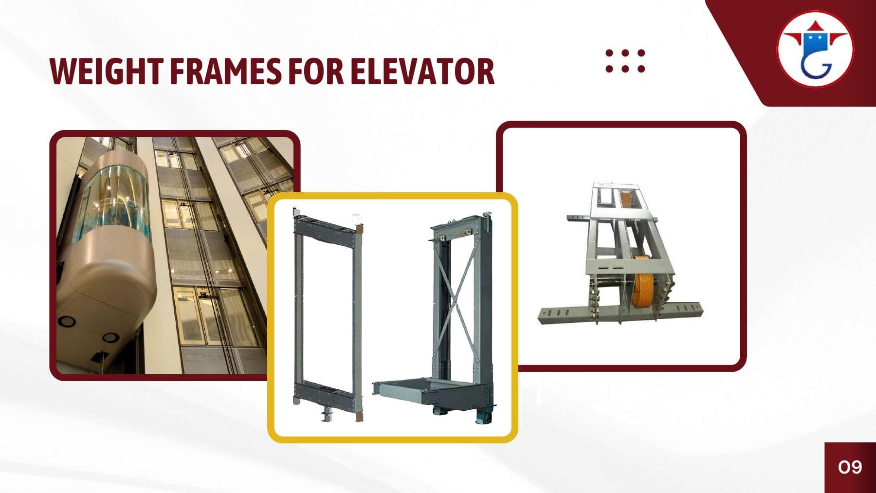
TKE and Eros Elevators are the lift references on our customer list, and the door panel, handrail and frame work for those programmes is where the flatness and gap values here come from. Welded elevator counterweight frames covers the frame side of the same assembly, and the elevator parts page lists the part families we make. Both plants run to ISO 9001:2015 and ISO 14001:2015.
We do not issue fire ratings, and we do not glaze vision panels. A fire-rated door assembly is certified as a system by the OEM, and the glass is a bought-in item fitted by the door assembler.
What the lift drawing has to settle
- Panel size, handedness and which face is the lobby face.
- Skin thickness, material grade and the standard (IS 513 for CRCA, IS 6911 for stainless).
- Return depth on each edge and the corner relief.
- Flatness limit, the face it is measured on and the measurement method.
- Squareness tolerance measured on the diagonal.
- Hanger bracket hole pattern, slot direction and adjustment range.
- Door gap and sill clearance, with the coating build accounted for.
- Coating system, colour, DFT, which faces are coated, and the masking schedule.
- Maximum panel mass for the hanger and roller rating.
The RFQ checklist collects these fields, and the elevator and lift component guides cover the hangers, frames and sills this panel fits between.
When a fabricated panel is the wrong choice
A fire-rated door, a door with a large vision panel, or a door that has to carry a specific acoustic rating is a system, not a panel. We can make the steel to the OEM drawing, but the rating comes from the assembly and its test, and the certificate holder has to be the door OEM.
A stainless door in a brushed finish shows flatness more than a painted one, because the reflection is specular. If the lobby design calls for mirror stainless, expect a double skin and a flatness target of 1.0 mm, and expect to pay for the polishing. We form and weld stainless, but mirror polishing is an outside operation quoted separately.
And a door panel narrower than about 500 mm, such as a telescopic leaf, is usually better made as a formed profile with an integrated stiffener than as a tray, because the returns take up too much of the face width.
Send the door drawing with the shaft dimensions and the finish sample through request a quote, and the panel comes back with the flatness method and the gap stack agreed before the first blank is cut.
Frequently asked questions
What thickness is an elevator landing door panel?
1.2 mm CRCA for doors up to 1,100 mm wide, with 40 mm folded returns on all four sides. Above that width, either a 1.6 mm skin or a mid-height stiffener, because a 1.2 mm panel at 1,400 mm wide drums at door-closing frequency.
What flatness can a landing door panel hold?
1.5 mm over a 2,000 mm height, measured on the lobby face with the panel standing on a surface plate. Under 1.0 mm is achievable on a double-skin panel; a single skin with returns usually lands between 1.0 and 1.5 mm.
Why does the door gap change after painting?
Powder at 60–80 µm on the panel edge and the door frame closes the gap by about 0.14 mm. If the drawing gives a 4.0 mm maximum gap, the coated door can be outside it before anyone adjusts the hanger.
Do you make fire-rated landing doors?
We fabricate and coat the steel panel to the OEM's drawing. Fire rating belongs to the assembled door and its certificate, which the lift OEM holds; a panel alone cannot carry a fire rating.
Can the panel be supplied in stainless steel?
Yes, in 1.2–1.5 mm 304 to IS 6911 with a brushed or 2B finish. Stainless panels are formed and welded the same way but need the weld tint removed before packing, and they show flatness defects more than a painted panel.
Sources and further reading
- ISO 8100-1:2019 — Lifts for the transport of persons and goods, safety rules for construction and installation · reviewed 3 Nov 2026
- IS 14665 — Electric traction lifts, code of practice (installation and clearances) · reviewed 3 Nov 2026
- ISO 2409:2020 — Paints and varnishes, cross-cut test for coating adhesion · reviewed 3 Nov 2026
Send the door drawing and the shaft dimensions
Include the panel size, skin thickness, return depth, finish and the clearance you need at the sill. We review the forming and coating route before quotation.
Request a quote