Key takeaways
- A sharp laser-cut 90° edge holds 40–60% of the face film, so an 80 µm face coat leaves only 30–45 µm at the corner where corrosion starts.
- Remove the 5–20 µm laser oxide on mild steel by blasting to Sa 2½ or pickling before pretreatment; alkaline cleaning alone leaves it in place.
- Specify an edge radius of R0.5 minimum for C3 service and R1.0–2.0 for coastal or C4 environments, and state the burr limit at 0.1 mm.
- Judge the result by scribe and edge creep after 480 h neutral salt spray, not by face gloss; creep over 2 mm is a preparation failure, not a powder failure.
The first rust on a coated sheet-metal part appears at a laser-cut edge, not in the middle of a face. An 80 µm face coat thins to 30–45 µm at a sharp corner, and under that thin film sits 5–20 µm of laser oxide that never stopped being hygroscopic. Together they give a corrosion cell that runs from the edge inwards.
Powder coating laser-cut edges is therefore a preparation problem before it is a powder problem. This article covers what the cutting process leaves on the edge, how much film actually lands there, which preparation route removes the oxide without adding cost you cannot recover, and the numbers to put on a drawing so the edge is inspected rather than assumed.
The part in the worked example is a 3 mm CRCA bracket, 480 h neutral salt spray, outdoor installation — the same duty as a genset base-frame bracket or an elevator sill support.
What a laser actually leaves on the cut face
A fibre laser cutting 3 mm CRCA with oxygen assist leaves four things on the edge: an oxide layer of 5–20 µm, a recast layer of similar thickness that is harder and more brittle than the parent metal, a dross bead of 0.05–0.2 mm on the underside, and an edge roughness of Ra 2–6 µm. A sheared edge, for comparison, is 0.8–1.6 µm and carries no oxide at all.
The oxide is the problem. It is porous, it absorbs moisture from the air, and it is brittle enough to crack under the film, so moisture reaches bare steel at every crack and starts a cell between the oxide and the metal. In Mumbai between June and September, when relative humidity sits above 80% for weeks, an unprotected laser-cut edge shows flash rust within 24–48 h of cutting. A part that waits three days between the laser and the pretreatment line is already starting behind.
Stainless steel behaves differently. Cut with nitrogen assist, it leaves a bright, nearly oxide-free edge with a 1–3 µm nitride layer and a work-hardened zone 10–20 µm deep. That edge coats well and does not need pickling unless the part is also welded. Aluminium leaves 1–5 µm of oxide and a dross bead on the exit side, and brass and copper leave a recast edge that is visibly rougher than the face.
Does the whole part need blasting, or only the edge?
Only the surface that will be coated, which means the whole part, because a laser-cut profile has edges on every side. There is no practical way to blast an edge and leave the face untouched on a 3 mm bracket, and there is no need to: blasting also gives the anchor profile that helps conversion coating and powder key to the steel.
Three routes remove laser oxide, and they cost differently.
Shot blasting to Sa 2½. ISO 8501-1 defines Sa 2½ as a very thorough blast cleaning in which only light shadows, streaks or spots of the original surface remain. Our 16 ft × 16 ft chamber handles brackets, frames and panels in batches, and it produces a 0.2–0.5 mm edge radius as a side effect. Blasting is the cheapest option per square metre for parts above about 0.3 m².
Acid pickling. Hydrochloric or sulphuric pickling dissolves the oxide and leaves the edge geometry unchanged, which matters when a sharp edge is required for a fit. It adds a rinse and a waste stream, and it does nothing for dross.
Mechanical deburring. Vibratory bowls and brush heads remove dross and knock the edge back by 0.1–0.3 mm, but they polish the oxide rather than remove it on the face. Use deburring for the burr, and blasting or pickling for the oxide.
Doing both is common and correct: tumble the small brackets to break the dross in 15–30 minutes, then blast the batch to remove the oxide. The order matters, because blasting a dross bead drives it into the edge.
The numbers to write on the drawing
| Parameter | Typical value | Ganesh limit or note |
|---|---|---|
| Laser oxide, mild steel, O₂ cut | 5–20 µm | Removed by blasting to Sa 2½ or pickling before pretreatment |
| Recast layer | 5–20 µm | Reduced by nitrogen assist or a second pass |
| Dross height | 0.05–0.2 mm | Burr limit on drawing: 0.1 mm maximum |
| Edge roughness Ra | 2–6 µm | Anchor profile after blasting 3–6 µm |
| Film on a sharp 90° edge | 40–60% of face | 80 µm face gives 30–45 µm at the corner |
| Film on an R0.5 edge | 80–95% of face | Radius is cheaper than extra film |
| Film on an R2.0 edge | 95–100% of face | Specified for coastal C4 work |
| Sheet thickness range | 0.8–40 mm custom parts | 12 kW laser to 20 mm; iron worker 30–40 mm plate |
| Minimum hole for full coverage | ≥ 3 mm | Below 3 mm the film bridges and the hole closes |
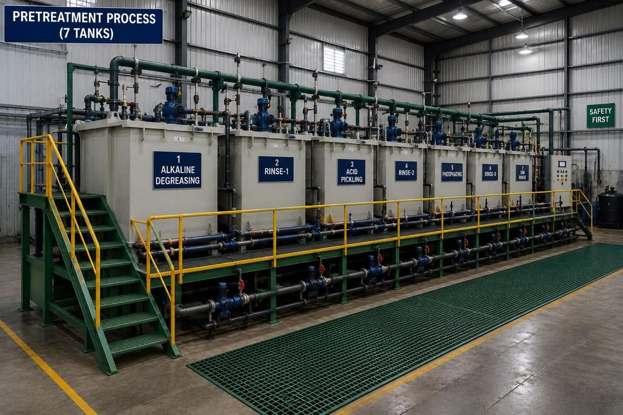
| Pretreatment | Seven-tank, conversion coated | In-house line, same route for steel and aluminium with separate schedules |
| Face film build | 60–80 µm | Eddy-current or magnetic DFT, nine points per part |
| Salt spray | 480 h NSS, edge creep ≤ 2 mm | Measured from the cut edge, worst point, not average |
| Service class | C3 default; C4 coastal | Set by ISO 12944-2 environment, not by the drawing title |
The Ganesh column is where we can and cannot help. Blasting, pretreatment and coating run in-house; if the drawing calls for acid pickling instead of blasting, say so at enquiry so the route is confirmed rather than assumed. We cannot hold a 0.1 mm burr limit on a 12 mm plate cut without a secondary operation either: at that gauge the dross is heavier and the edge needs milling or a heavy chamfer, which we will flag at quotation rather than quietly price in.
Why the powder pulls back from a sharp edge
Powder coating is a line-of-sight process. Charged particles of 20–40 µm follow the electrostatic field to the nearest grounded surface, and a 90° corner presents almost no area to the gun. What arrives there is a fraction of the face build; what survives the cure is less again, because surface tension pulls the molten film away from a sharp arris.
The measured result is consistent: 40–60% of face film at a sharp corner, 80–95% at R0.5, and effectively full thickness at R2.0. On a 3 mm bracket with an 80 µm face, the sharp corner therefore carries 30–45 µm — below the 60 µm that most C3 specifications assume.
The same geometry effect appears inside recesses. A 10 mm wide, 20 mm deep channel sees 20–30 µm on its inner walls, a 25 mm deep box section less, and a 2 mm hole closes entirely. This is the Faraday cage effect, and no gun setting removes it. Design it out with radius, or coat the inside with a different process.
The radius costs less than the film
Adding R0.5 to a laser path is almost free: an arc replaces a sharp corner in the DXF, and the laser adds a fraction of a second per corner. Doubling the film to reach the same edge thickness is not free, because powder consumption scales with area and thickness, and a 140 µm face film cracks on assembly. For any part rated C3 or worse, radius first.
Three preparations, one salt spray result
The table above is a specification; this is what the preparation does on a panel. Three 3 mm CRCA coupons from the same sheet, coated in the same batch at 75 µm face film, tested to ISO 9227 neutral salt spray for 480 h:
- degreased only, sharp edge: 4–6 mm of creep from the cut edge, with red rust visible along the arris by 240 h;
- blasted to Sa 2½, sharp edge: 1.5–2.5 mm of creep, red rust starting at 360–480 h;
- blasted to Sa 2½, R0.5 edge: 0.5–1.5 mm of creep, no red rust at 480 h.
The middle case is the one that catches buyers. Blasting alone removes the oxide and roughly halves the creep, which is enough to pass a loose specification and not enough to survive a coastal site. The edge radius is what carries the last millimetre.
Why dross matters more than it looks
Dross forms when molten metal is not fully ejected from the kerf and resolidifies on the underside. At 0.05–0.2 mm it is thin enough to pass a visual check and thick enough to hold the film off the edge, leaving a hollow under the coating. It also creates a crack initiation point when the part is clamped or bolted. A 0.1 mm burr limit on the drawing, checked with a burr gauge or a fingernail drag, is a two-minute inspection that prevents a five-year corrosion argument. Parts that go to a vibratory bowl before blasting normally meet it without a manual operation.
Racking changes the edge as much as the gun
Two identical brackets hung in the same booth can differ by 15 µm at the edge. A part hung with its cut edge facing the gun collects more powder there; a part hung flat, with the edge in its own shadow, collects less. Large flat panels are the worst case, because the edge faces sideways while the gun sweeps the face. If edge film is critical, say so and ask for the first-off part to be measured at the edge, not just the face. A coater who knows the edge is being measured will rack for it.
The crossover to zinc-rich primer
Above C4 — coastal sites, chemical plants, wash-down areas — radius and powder alone are marginal on a 1.5–2 mm edge. The conventional answer is a zinc-rich primer stripe on the edge before the powder, or a duplex system over hot-dip galvanising. We do not hot-dip galvanise in-house; a duplex specification needs a galvaniser in the chain, and the powder then has to be compatible with the galvanised surface. Say so at enquiry, because it changes the route and the lead time.
Preparing stainless, aluminium and galvanised edges
Stainless. A nitrogen-cut 304 or 316 edge needs no pickling unless it has been welded; the weld heat tint does need pickling or a pickling paste, because chromium-depleted zones under heat tint corrode first. Keep stainless off carbon-steel blasting media, since embedded iron particles rust on the surface within weeks.
Aluminium. Blast with non-ferrous media only. A steel grit that has run CRCA will leave iron traces in an aluminium edge, and those traces produce pinpoint corrosion under the film. Radius to R0.5 as with steel; aluminium edges thin in the same proportion.
Galvanised sheet. Cutting exposes the steel core along the edge, and that core is what rusts. The zinc around the cut provides some sacrificial protection, but a powder film over an exposed 1.5 mm core will still show red rust at the edge in a salt spray. A zinc-rich touch-up on the cut edge, or a design that keeps cut edges out of water traps, is the usual answer.
What Ganesh actually runs
Edges here come off a 12 kW fibre laser with a 40 ft × 16 ft bed, which cuts CRCA, stainless, aluminium, brass and copper up to 20 mm, with 6 kW and 3 kW support machines for thinner work and a 250 T punching press for hole-intensive panels where punching beats a laser on cost. Oxide removal and edge radiusing run through the 16 ft × 16 ft shot blast chamber, and coating through seven-tank pretreatment, the 18 ft × 14 ft powder booth and the curing oven, with DFT and cross-hatch adhesion checked on the line.
That route exists because the failure we see most often on returned parts is edge creep on a part whose face film measured correctly. The shot blasting capability page sets out what the chamber handles, and the paint shop page covers the tanks that follow it.
What the finish specification has to settle
- Edge radius, as a note plus a detail: R0.5 minimum for C3, R1.0–2.0 for C4, with the corners called out on the profile.
- Burr and dross limit, typically 0.1 mm maximum, measured on the exit side.
- Surface preparation before coating: blast to Sa 2½, pickle, or deburr only, with the standard named.
- Film build on the face and the minimum acceptable at the edge, measured 0.5 mm from the arris.
- Corrosion test: salt spray hours, the standard, and the creep limit measured from the edge rather than from a scribe on the face.
- Service environment class, so the coater can challenge the specification if the numbers do not match the duty.
- Hole and slot sizes, if any are below 3 mm and must stay open after coating.
If the edge condition is still open, the deburring and edge quality article covers what each finishing route achieves, and the powder coating cost estimator shows what a 20 µm film increase costs per part. The surface treatment hub indexes the pretreatment and failure articles, including why powder coating fails on outdoor enclosures.
When this route is wrong
Four cases where a laser edge plus powder is the wrong answer.
Heavy plate in a wet environment. At 8 mm and above, a sharp laser edge cannot be radiused economically and powder cannot cover it. Hot-dip galvanise the part first, or use a different joint design that keeps the cut edge out of the weather.
Edge coverage is the acceptance criterion. Electrophoretic coating deposits 20–25 µm uniformly on edges and inside box sections, which powder cannot match. If the customer's test is edge creep under 1 mm, e-coat is the process, and we would rather say that than quote a route that fails.
Holes below 2 mm. They close, and no film specification reopens them. Drill after coating, or accept the closure in the design.
Parts that cannot be blasted. A precision-machined face on a laser-cut blank cannot go through a blast chamber without masking. Either mask it, pickle instead, or move the machining after coating.
Send the drawing with the burr and radius notes to request a quote, so the preparation can be priced as its own operation rather than buried in the piece rate.
Frequently asked questions
Do I have to remove laser oxide before powder coating?
On mild and alloy steel, yes for anything rated C3 or worse. The 5–20 µm oxide is porous, hygroscopic and conductive, so moisture under the film starts creep from the edge within months. Blasting to Sa 2½ or acid pickling removes it; degreasing does not.
How thick is powder on a laser-cut edge?
On a sharp 90° corner the cured film is typically 40–60% of the face thickness, so an 80 µm face coat leaves 30–45 µm at the edge. A R0.5 radius lifts retention to 80–95%; a R2.0 radius is effectively full thickness.
Can I leave the laser edge sharp if the part is indoors?
Indoors in a dry, controlled room (C1–C2), a sharp edge with 60 µm of powder is usually acceptable. Any condensate, wash-down or monsoon humidity moves the part to C3 and the edge becomes the first failure point.
Does nitrogen cutting give a better coating edge than oxygen cutting?
For stainless steel, nitrogen gives a nearly oxide-free edge with only a 1–3 µm nitride layer, which coats well. For mild steel, nitrogen reduces dross and oxide but doubles or triples cut time; blasting after oxygen cutting is usually cheaper than cutting the whole part on nitrogen.
Why does the powder bridge over small holes?
Powder particles are 20–40 µm and the film pulls back at sharp internal edges. Holes under about 3 mm close or reduce to 70% of nominal after a 70 µm coat, which matters on perforated panels and vent slots.
Sources and further reading
- ISO 2409:2020 — Paints and varnishes, cross-cut test · reviewed 3 Nov 2026
- ISO 9227:2022 — Corrosion tests in artificial atmospheres, salt spray tests · reviewed 3 Nov 2026
- ISO 12944-5:2019 — Corrosion protection of steel structures by protective paint systems, protective paint systems · reviewed 3 Nov 2026
Send the part with its edge condition
Add the burr limit, the radius and the environment to the drawing. We review edge preparation against the cut route before quoting.
Request a coating quote