Key takeaways
- Size the louvre on net free area, not opening size: keep face velocity at 4–6 m/s, because above about 7 m/s rain droplets pass through and pressure drop rises sharply.
- A 45° single-bank blade at 75–100 mm pitch gives 40–55% free area; add a second opposed bank only where the site faces driving rain, and expect free area to fall to 30–40%.
- Weld or rivet blades at mid-span every 500–600 mm; end-welded blades alone resonate with engine vibration and crack at the root within a season.
- Hold frame diagonal to ±1.5 mm and blade pitch to ±1 mm so a replacement panel fits a canopy already in the field.
- Powder cannot reach a gap under about 8 mm, so keep blade-to-blade clearance above 8 mm and specify masking before the booth, not after.
A canopy louvre looks like the easiest panel on the set: a frame, thirty blades and four bolting holes. It is the panel that most often comes back. Two failures dominate — the bank starves the radiator of air on a 45 °C site, or driving rain reaches the alternator through a blade line that looked sealed on the drawing.
Both are decided by numbers that a genset canopy louvre panel design usually leaves off the drawing: net free area, blade angle, blade overlap and the pitch of the blade fixings. A 500 kVA set with a radiator fan moving 2.8 m³/s through a 1.2 m × 1.0 m opening and a 40% free-area bank has 0.48 m² of net open area, so the face velocity is 2.8 ÷ 0.48 = 5.8 m/s. That is inside the working band. Take the same fan and a 25% bank and the velocity reaches 9.3 m/s, which is where water separation fails and static pressure climbs.
This guide sets out the four decisions that govern genset canopy louvre panel design, the tolerances worth putting on the drawing, and where the panel is the wrong way to ventilate. The manufacturing context sits in the genset and canopy hub.
What free area does a canopy louvre actually need?
Size the bank on net free area and keep face velocity between 4 and 6 m/s. Net free area is the frame opening multiplied by the free-area ratio of the blade bank, not the opening itself.
The ratio depends on geometry. A 45° blade of 100 mm pitch and 1.2 mm thickness blocks a projected depth of about 70 mm, leaving roughly 40–55% open depending on how the blades are pressed and how the ends are framed. A double bank — two sets of blades opposed to each other — drops the ratio to 30–40% and is the usual fix for a coastal site with monsoon-driven rain.
Velocity is the number that matters, because it drives both pressure drop and droplet carry-over. Air accelerates through the free area, and droplets with enough momentum follow the airstream round the blade rather than falling out of it. In practice, a single bank holds water up to about 6 m/s of face velocity and starts to pass a visible mist above 7 m/s.
Work the sum backwards for a new set. Take the radiator fan curve at the site ambient, not at 25 °C. A fan quoted at 3.2 m³/s at standard conditions can deliver 2.6 m³/s at 45 °C and 600 m altitude, and a louvre sized on the first figure will be undersized in service. Add the louvre's own pressure drop to the fan static and check that the operating point still sits on the right side of the curve. Then add the exhaust side: an exhaust bank smaller than the intake bank is a common mistake, because hot air expands and the discharge volume is 5–10% higher.
Louvre geometry: the numbers a genset canopy louvre panel design has to carry
The table below is the set of values we work to when a customer drawing shows "louvre as per sample" and asks for a manufacturable panel. Values in the first two columns are typical industry practice; the third is what we can hold at Ganesh.
| Parameter | Typical value | Ganesh limit or note |
|---|---|---|
| Blade material and thickness | 1.2–1.6 mm CRCA, 1.6–2.0 mm border frame | Cut on the 12 kW fibre laser; formed on the 200 T brake with a 4,450 mm bed |
| Blade angle | 30–45° from horizontal | 45° for rain rejection, 30° where free area is tight; angle held to ±2° |
| Blade pitch | 75–100 mm | Pitch held to ±1 mm measured between blade noses |
| Free-area ratio | 40–55% single bank, 30–40% double bank | Calculated from the CAD section and confirmed on the first article |
| Face velocity | 4–6 m/s | Above 7 m/s we flag droplet carry-over on the drawing review |
| Blade overlap in plan | 10 mm minimum | Set by the fold depth; below 10 mm there is line of sight through the bank |
| Blade-to-blade gap | 8 mm minimum | Below 8 mm electrostatic powder bridges the gap and closes the slot |
| Frame diagonal | ±1.5 mm on a 1.2 m frame | Checked on a surface plate or with a steel tape corner to corner |
| Hole position | ±0.5 mm | Tighter by agreement on fixing holes shared with an existing canopy |
| Panel flatness | 1.5 mm over the frame face | Beyond this the gasket line against the canopy body leaks |
| Coating build | 60–90 µm powder | Measured with a DFT gauge on blades and frame, measured after cure |
Two entries in that table decide most disputes. The first is the gap. A 6 mm slot looks generous on screen and is closed by the time two coats of powder have cured on both faces. The second is the overlap: a blade that does not overlap its neighbour in plan leaves a straight line of sight from the outside to the radiator core, and no amount of blade angle compensates for it.
How is free area checked on the first article?
Measure the panel, do not trust the model. A first-article check on a louvre reads four dimensions and then does one sum.
Measure blade pitch across at least ten blades and divide by nine, because a single pitch reading hides a progressive drift. Measure the blade angle with a digital protractor against the frame face. Measure the clear gap between opposing blade edges with a set of gap gauges. Count the blade openings and record the frame opening. Then compute net free area as the sum of the clear projected gaps multiplied by the inner frame width, and compare it with the figure on the drawing. A 3 mm error in pitch across thirty blades moves the total open height by 90 mm, which is 7% of a 1.2 m frame and enough to change the face velocity by half a metre per second.
The second check is visual and worth doing on every panel rather than the first. Stand on the outside of the panel at eye level to the blade line and look through. If any part of the radiator core, the alternator or a light source behind the canopy is visible in a straight line, the overlap is short and the bank will pass water at the first driving rain. The third is a water test: play a hose at 2 bar across the outside face at 45° for two minutes and check the inner face for droplets. Sheet-level trials cost an hour; a wet alternator costs a set.
Where louvre panels fail in service
Four failure modes account for nearly every louvre complaint we see, and each has a physical cause that can be designed out.
Blade rattle and root cracks
A blade welded only at its two ends behaves as a beam with a first natural frequency in the 20–60 Hz band, which is exactly where a four-pole genset at 1,500 rpm excites it. The blade flutters, the weld toe at the end of the slot works, and a crack starts within a few hundred hours. The fix is mechanical: add a mid-span weld, rivet or a folded stiffening lip at 500–600 mm intervals. On a 1.2 m panel that is one mid-span fixing per blade, and it changes the natural frequency by more than an octave.
Distortion from welding the frame
Louvre frames are thin, long and welded at the corners, which is a recipe for a twisted panel. Weld the corners in a fixture, alternate the sequence, and keep the heat input low; a 3 mm fillet run along a 1.6 mm frame corner pulls the frame out of flat before the panel reaches the paint line. Panels that arrive at the booth twisted come out of the oven twisted, because powder cure at 180–200 °C releases the residual stress that the fixture was holding.
Paint bridging between blades
Powder is applied electrostatically and wraps around edges, which is an advantage on a canopy and a problem inside a louvre. Below an 8 mm gap the wrap from opposing faces meets in the middle and the slot closes. Keep the gap above 8 mm, hang the panel with the blades vertical so overspray falls away, and check the first article by passing a gauge through every slot.
The frame interface and the gasket line
A louvre panel is usually bolted over an opening in the canopy side, with a strip gasket or a mastic bead between the two. That joint is where a panel that measured perfectly still leaks. Keep the return flange at least 20 mm wide so the gasket has a land to sit on, keep the flange free of welds and spatter, and specify a flat land rather than the fold radius, because a gasket compressed over a radius takes a set and stops sealing. On a panel wider than 1 m, add a fixing at mid-span on each long edge; the panel will otherwise bow away from the gasket under wind load and pull the bolts loose over a season.
Hot air recirculation
A discharge bank facing the intake bank at 1 m separation will pull its own hot air back into the set, and the set derates without any obvious fault. Specify a minimum 1.5–2 m separation between intake and discharge, or duct the discharge away from the intake face. On a canopy where the two banks must share a side, use a baffle and offset the banks vertically.
How the panel is built at Ganesh
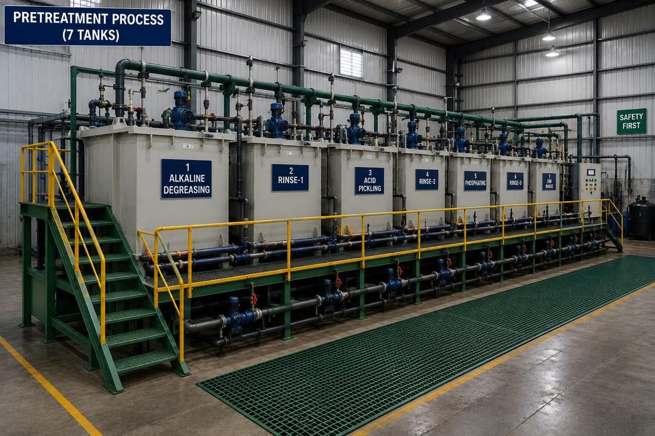
The route for a canopy louvre at Ganesh runs laser cut, form, fixture weld, seven-tank pretreatment, powder coat and oven cure, all inside the same plants. Blade blanks and the border frame are cut on the 12 kW fibre laser on a 40 ft × 16 ft bed, which lets a full-length louvre bank for a large canopy come off in one piece rather than three bolted sections. Blades are formed on the 200 T, 5-axis CNC press brake with a 4,450 mm bed, using a Delem programme that stores the blade angle for repeat orders.
Frames are welded in fixtures built in our own tool room, with the blade bank tacked at the ends first and the mid-span fixings added after the frame is released, so the panel is not fighting the fixture when it cools. Welded assemblies go through the 16 ft × 16 ft shot blast chamber where the specification calls for a blast profile, then the seven-tank pretreatment line, then the 18 ft × 14 ft electrostatic powder booth and the curing oven. Coating thickness and adhesion are checked with a DFT gauge and a cross-hatch test.
The louvre panel is usually one line item in a larger canopy kit. Our genset parts programme covers the canopy, acoustic panels, doors, base frame and control panel enclosure as one coated supply, which is how we build for Mahindra Powerol. Panels and their formed sections are also covered in bending for genset canopies and panels and in the laser-cut canopy work described in laser-cut components for genset canopies.
How much noise does the louvre let through?
Assume the louvre is the weakest path and design the rest of the canopy around it. A single 45° bank of 100 mm blades gives roughly 5–8 dB(A) of insertion loss between 500 Hz and 2 kHz. A double bank with an absorbent splitter between the rows reaches 12–18 dB(A) in the same band, at the cost of free area and pressure drop.
In India the governing figure is the CPCB noise limit for diesel generator sets, which sets 75 dB(A) at 1 m for sets up to 1,000 kVA under the Environment (Protection) Rules, 1986. A canopy that meets 75 dB(A) at 1 m is doing 25–35 dB(A) of attenuation against an unenclosed set, and the louvre bank contributes a few dB(A) of that. The bulk comes from the acoustic lining, the door seals and the panel stiffness. Treating the louvre as the acoustic solution is a design error; treating it as the leak that must not undo the lining is correct.
If a customer specifies an insertion loss figure, ask for the test method. ISO 7235 covers laboratory measurement of ducted silencers, and a louvre measured in a wall opening is not the same test. Without a method, the number is a claim rather than a specification.
What the canopy drawing has to settle
- Net free area in m², with the fan volume at site ambient in m³/s and the resulting face velocity.
- Blade section: thickness, fold depth, angle and pitch, with the overlap dimension called out in plan.
- Fixing method for blades: weld, rivet or fastener, and the mid-span pitch.
- Gap between blades after coating, stated as a minimum, not a nominal.
- Frame interface: hole pattern, bolt size, gasket groove or flat land, and the diagonal tolerance.
- Coating system: powder type, colour, target DFT in µm, and any masking on the fixing faces.
- Marking: an airflow arrow on the panel, because louvres get fitted upside down on site.
The canopy RFQ checklist takes these fields in order and returns the questions we would ask anyway, so the first quotation comes back without a clarification loop. Where the panel is part of a coated assembly, the finish schedule is worth reading against why powder coating fails on outdoor enclosures, because a louvre shows coating defects sooner than any flat panel.
When a louvre is the wrong answer
A louvre bank is the wrong choice when the free area needed exceeds about 60% of the wall it sits in, when the site faces sustained wind-driven rain, or when the noise target needs more than 15 dB(A) of path attenuation. In those cases the alternatives are a ducted inlet with a weather hood, a motorised damper with a rain sensor, or a splitter silencer with an aerodynamic profile. Each adds cost and pressure drop, and each is a different drawing.
We do not design the acoustic package, select the radiator fan, or test a completed canopy to a noise standard. Those sit with the genset OEM and its acoustic consultant. What we do is manufacture the panel to the free area and geometry the OEM specifies, hold the tolerances in the table, and tell you when a drawing cannot deliver the free area it asks for. That conversation is cheaper before the tooling than after the first monsoon.
Frequently asked questions
What free area should a genset canopy louvre have?
Match the radiator fan volume to net free area so face velocity stays between 4 and 6 m/s. A 2.8 m³/s fan through a 1.2 m² opening needs about 0.5 m² of free area, which is roughly 40% of the opening.
How much noise does a louvre actually reduce?
A single 45° bank with 100 mm blades gives about 5–8 dB(A) insertion loss in the 500–2000 Hz band. The acoustic lining and the door seals do most of the work; the louvre is the leak you are managing.
Can a louvre panel be welded or must it be riveted?
Both are used. We fixture-weld blade banks in CRCA and use rivets where the blade is thin or replaceable. Either way, fix the blades at mid-span every 500–600 mm as well as at the ends.
What thickness is a canopy louvre blade?
1.2–1.6 mm CRCA is the working range, with a 1.6–2.0 mm border frame. Below 1.2 mm the blade deflects under fan pressure and the paint film starts to craze at the fold.
Sources and further reading
- Central Pollution Control Board — noise limits for diesel generator sets · reviewed 3 Nov 2026
- IS 513 — Cold reduced carbon steel sheets and strips (CRCA grades) · reviewed 3 Nov 2026
- ISO 2768-1 — General tolerances for linear and angular dimensions · reviewed 3 Nov 2026
Have a louvre panel drawing ready?
Send the panel drawing, the radiator airflow and the site noise target. We will return the free area calculation with the quotation.
Request a quote