Key takeaways
- Powder is line-of-sight: a recess 20 mm wide and 40 mm deep typically holds 20–30 µm on its walls against 60–80 µm on the face, and a 10 mm slot holds less.
- Every enclosed volume needs a drain of at least 8 mm at its lowest point; a 500 × 400 mm tray with a 25 mm upstand holds 5 litres of pretreatment chemistry.
- Specify 60–80 µm on the face and at least 40 µm in any recess that must pass a C3 salt spray, and measure both with a DFT gauge per ISO 2808.
- Cure to 180–200 °C metal temperature for 10–15 minutes; a sealed cavity outgasses through the film at cure and leaves pinholes that no film thickness fixes.
A 300 mm deep enclosure with 25 mm return flanges comes out of the booth with 85 µm on the front face and 25 µm inside the channel. The face passes the gauge check. The channel fails salt spray at 240 hours, because 25 µm is less than half the film the specification assumed and the inner corner never saw the gun.
Design for powder coating is line-of-sight engineering with a drainage problem attached. The process deposits charged particles on grounded metal, so it coats what it can see and thins where the field is shielded. It also drags chemistry into every pocket the part carries from tank to tank. Both are decided in CAD, not in the booth.
The reference part is a 1.5 mm CRCA enclosure, 500 × 400 × 300 mm, C3 outdoor duty, 60–80 µm polyester powder. The numbers below apply to that class of part; heavier plate changes the drainage volume, not the logic.
What does design for powder coating control?
Three variables: line of sight into recesses, drainage of every enclosed volume, and film build across the surface.
Line of sight sets the minimum film inside a box or channel. Drainage sets whether the pretreatment chemistry leaves the part before the oven. Film build sets the corrosion life and the assembly fit. A drawing that fixes all three is a coating specification; a drawing that says "powder coat, 60–80 µm, black" is a wish.
The corrosion class comes first, because it decides which of the three matters most. ISO 12944-2 defines C1 to C5 corrosivity categories by the environment, not by the product. A C2 indoor panel can live with 40 µm in a recess. A C4 coastal panel cannot, and the design has to open the geometry until the gun reaches the surface.
The Faraday shadow
A recess shields itself. Powder particles follow field lines to the nearest grounded surface, and a cavity presents a weak field at its back wall, so the film thins with depth. The measured pattern is consistent across booths:
- a 20 mm wide, 40 mm deep channel: 20–30 µm on the walls;
- a 10 mm wide, 30 mm deep slot: 10–20 µm, often with a bare strip at the back;
- a 5 mm slot, 20 mm deep: effectively uncoated beyond the mouth;
- an open 90° internal corner: 50–70% of the face film, worse if the corner is sharp.
The design rule is a ratio. For full film, keep the slot width at least 1.5 times its depth. For a 40 µm minimum, width equal to depth is the limit. Below that, either open the section, split the part, or specify a different coating for the inside.
Drainage and drag-in
A pocket does two things: it carries chemistry from one tank to the next, and it holds rinse water into the oven. Both show up as defects that look like powder failures.
A 500 × 400 mm tray with a 25 mm upstand holds 5 litres. That is 5 litres of alkaline cleaner dragged into the rinse, then into the conversion coating, then into the oven. The bath contaminates, the part dries with streaks, and the film blisters where the water boiled under it. One missing drain hole can upset a whole batch, not just one part.
The drain rule is 8 mm minimum at the lowest point, one per enclosed volume, with the part tilted 5–10° on the rack. A 6 mm hole bridges with powder on a 60 µm coat and holds water by surface tension before that. A blind hole deeper than twice its diameter traps chemistry even when it is vertical; a 10 mm diameter, 30 mm deep hole holds 2.4 ml.
Vent and drain are a pair. A hollow section needs a hole at its highest point for air to leave and one at its lowest for chemistry to leave. A single hole fills and empties through the same path, which works only if the hole is large enough to break the air lock. On a 40 × 40 mm tube, 12 mm at each end is the practical minimum; on a folded box, one 8 mm drain at the low corner and one 8 mm vent at the high corner is enough.
Geometry rules that keep the film honest
Recesses and box sections
Open the end of a box, or split it into a wrapper and two end caps that coat flat. A 300 mm deep box with one open face coats to 50–60 µm on the inner walls near the mouth and 20–30 µm at the back. If the inside is a cable chamber that never sees weather, that may be acceptable. If it is an outdoor enclosure, it is not.
Where a recess must stay closed, add a 45° chamfer or a radius at the internal corner. A R2.0 internal radius lets the field wrap into the corner; a sharp corner has no surface facing the gun.
Holes, slots and perforations
Powder bridges small openings. A 3 mm hole under a 70 µm coat closes or reduces to about 70% of nominal, and a 2 mm hole closes entirely. If the hole is functional — a drain, a fastener clearance, a ventilation path — either enlarge it to 5 mm minimum or drill it after coating.
Perforated panels are the extreme case. A 60% open area perforated sheet coats on the land between holes and bridges at the hole edges, so the open area falls. Specify the post-coat open area, not just the pre-coat pattern.
Edges and bends
A sharp laser-cut edge holds 40–60% of the face film. Radius to R0.5 for C3 and R1.0–2.0 for C4, and put the radius on the flat pattern so the laser cuts it rather than the brake crushing it.
Bending after coating is not an option on powder: the film cracks at the bend and the crack runs along the grain. Bend first, coat second, and keep weld spatter and burrs off the face that will be seen.
Grounding and racking
The part must be grounded through the rack, and the contact point must be bare metal. A hook carrying cured powder from the last cycle insulates the part, the film builds unevenly, and the operator turns up the voltage to compensate. Clean hooks and a dedicated contact pad, masked on the drawing, are part of the design.
Racking also decides which faces see the gun. A large flat panel hung vertically coats evenly on both faces; the same panel hung flat collects powder on the top face and almost none on the underside. If both faces are specified, say so, and expect a rack mark on one of them.
What the film weighs, and why uneven build costs twice
A 300 × 400 mm panel face is 0.12 m². At 80 µm and a cured density of about 1.5 g/cm³, the film on that face is 14.4 g. A booth running 60% transfer efficiency sprays 24 g to land 14.4 g, and the rest goes to the recovery system or the booth walls.
Doubling the film to solve a coverage problem doubles the powder, the overspray and the booth cleaning, and it produces a 120–160 µm film that cracks when the panel is bolted. The cheaper fix is geometric: open the recess, radius the corner, or split the part so each face sees the gun.
Aluminium, galvanised and pre-coated sheet
Aluminium takes powder well but needs its own pretreatment schedule. The natural oxide is 2–5 nm and keeps growing, so a chromate-free conversion coating is the usual base. Aluminium also expands more than steel at cure temperature, and a mixed-metal assembly can move at the joint and crack the film at the seam.
Galvanised sheet is harder. The zinc surface outgasses at cure, and the film pinholes over a weld or a cut edge unless the powder is specified for galvanised steel or a primer goes on first. Pre-coated sheet cannot be powder coated without stripping the coil coating, and the stripping usually costs more than the part.
Film build and cure numbers
| Parameter | Typical value | Ganesh limit or note |
|---|---|---|
| Face film, C3 | 60–80 µm | Measured with a DFT gauge per ISO 2808 |
| Recess film, 20 mm × 40 mm | 20–30 µm on walls | Below 40 µm, do not claim C3 inside |
| Recess width to depth for full film | 1.5 : 1 | 1 : 1 gives about 40 µm minimum |
| Minimum drain hole | 8 mm at the lowest point | 6 mm bridges; 5–10° rack tilt |
| Blind hole that traps chemistry | Depth > 2 × diameter | 10 mm × 30 mm holds 2.4 ml |
| Smallest hole that stays open | 3 mm | Below 3 mm, drill after coating |
| Edge film on a sharp 90° corner | 40–60% of face | R0.5 lifts it to 80–95% |
| Cure, metal temperature | 180–200 °C for 10–15 min | Per the powder data sheet, not the oven air |
| Overbake tolerance | About 10% over schedule | More yellows the film and embrittles it |
| Film above 100 µm | Cracks on bending and bolting | Do not thicken to fix a coverage problem |
| Salt spray, C3 system | 480 h, creep ≤ 2 mm | ISO 9227 neutral salt spray |
| Adhesion | Cross-cut Gt0–Gt1 | ISO 2409, checked at first article |
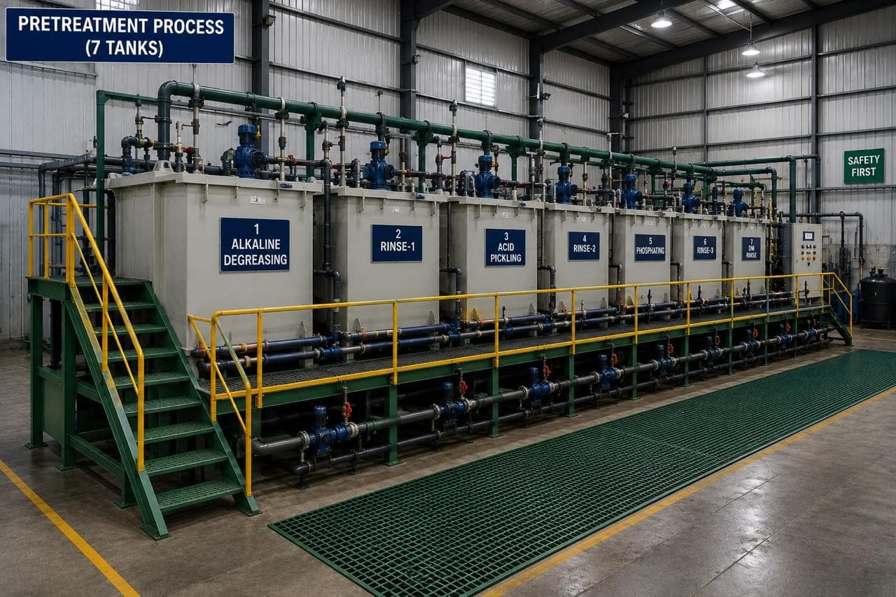
The Ganesh column is where the process can and cannot deliver. We run seven-tank pretreatment, an 18 ft × 14 ft powder booth, a wet paint booth and a curing oven, with DFT and cross-hatch checks on the line. We cannot put 60 µm inside a 10 mm slot with a conventional gun, and we will not write a specification that says we can.
What Ganesh runs
Coated parts go through the seven-tank line, then the 18 ft × 14 ft electrostatic booth, then cure, with the film measured on the face and at agreed recess points. Blasting runs in the 16 ft × 16 ft chamber when the surface needs an anchor profile or laser oxide removal. The paint shop page covers the tanks and the booth, and the shot blasting page covers what happens before them.
Parts for Godrej & Boyce, Eros Elevators and Gunnebo run through this route, including outdoor enclosures where the recess film is part of the first article. Where a drawing specifies 60 µm inside a closed box, the review flags it before quotation: the options are to open the geometry, split the part, or accept a lower internal film with a note on the drawing.
What to put on the drawing
- Corrosion class per ISO 12944-2, not just a colour and a gloss.
- Film build and measurement points per ISO 2808: face, recess, and edge if the edge is critical.
- Drain and vent holes with diameter and location, and the rack tilt if the part needs one.
- Smallest hole that must stay open after coating, and whether it is drilled before or after.
- Edge radius and burr limit, since the edge carries the thinnest film.
- Adhesion test per ISO 2409 and the acceptance grade.
- A note on sealed cavities: vented, split, or not coated.
For the edge condition that meets the film, powder coating laser-cut edges covers preparation and oxide removal. For the failure mode this article prevents, why powder coating fails on outdoor enclosures works from the corrosion site backwards. The design and CAD hub indexes the rest of the coating and geometry notes.
When this route is wrong
Powder is the wrong choice when the part needs a film inside a closed section, when the film must be under 40 µm, or when the substrate cannot take 180–200 °C.
A sealed electronics enclosure with a gasket land and a closed cable chamber should be split and coated before assembly, or coated with a process that reaches the inside. A part with a 1 mm perforation pattern that must stay open needs the holes laser-cut after coating or a different finish. A part with a heat-sensitive insert needs a low-temperature cure powder, and that is a supplier question, not a design assumption.
Where internal coverage is the acceptance criterion, electrophoretic coating deposits 20–25 µm uniformly on the walls of a box section. Powder cannot match that with a conventional gun. If the drawing needs 60 µm inside a closed box, the process is wrong, not the powder.
A part that needs a film on a surface the gun cannot see should be designed as two parts that coat flat, not quoted with a promise of internal coverage.
We do not claim full coverage inside a closed box, and we do not hide a thin recess behind a face measurement. Send the section and the corrosion class to request a quote and the coating route will be reviewed against the geometry before the first part is cut.
Frequently asked questions
Why does powder coating not cover the inside of a box?
The powder particles follow the electrostatic field to the nearest grounded surface, so a recess shields itself. A 20 mm wide, 40 mm deep channel typically measures 20–30 µm on its walls against 60–80 µm on the face, and a 10 mm slot gets less still. Design the box so the gun can see the surface, or accept a lower film specification inside.
What size drain hole does a powder-coated part need?
At least 8 mm at the lowest point of every enclosed volume, with a 5–10° tilt on the rack so gravity does the work. Below 8 mm the hole bridges with powder or holds chemistry by capillary action. A 25 mm upstand around a 500 × 400 mm tray holds 5 litres, which is why the drain is a design feature rather than a drill callout.
How thick should powder coating be?
60–80 µm on visible faces for a C3 environment, with 40 µm minimum in recesses that are exposed to the same conditions. Above about 100 µm the film cracks when the part is bent or bolted; below 50 µm the salt spray life drops sharply. Measure with a DFT gauge at defined points, not by eye.
Does powder coating cover sharp edges?
Only partly. A sharp 90° edge holds 40–60% of the face film, so an 80 µm face leaves 30–45 µm at the corner. Radius the edge to R0.5 minimum for C3 and R1.0–2.0 for coastal work, and specify the edge film if corrosion at the arris is the acceptance criterion.
Can I powder coat a sealed weldment?
No. Air inside the cavity expands at cure temperature and escapes through the film, leaving pinholes or a blister. Vent the cavity with a hole that stays open after coating, or split the weldment and coat the parts before assembly.
Sources and further reading
- ISO 12944-2:2017 — Corrosion protection of steel structures: classification of environments · reviewed 3 Nov 2026
- ISO 2808:2019 — Paints and varnishes: determination of film thickness · reviewed 3 Nov 2026
- ISO 2409:2020 — Paints and varnishes: cross-cut test · reviewed 3 Nov 2026
Send the part for a coating route review
Include the section, the drain and vent holes, and the corrosion class. We will flag the surfaces the gun cannot see before the drawing is released.
Request a quote