Key takeaways
- ISO 21920-1:2021 replaced ISO 1302 for indicating surface texture, and ISO 21920-2 and -3 replaced ISO 4287 and ISO 4288, so a drawing that cites ISO 1302 is citing a withdrawn standard.
- An Ra callout is incomplete without its cut-off: Ra 1.6 µm uses λc 0.8 mm and needs 4 mm of evaluation length, while a 2 mm laser-cut edge has 2 mm of surface and cannot carry the callout at all.
- Laser-cut CRCA edges measure roughly Ra 2–5 µm and sheared edges 6–12 µm; specify deburring, dross removal and a visual boundary sample instead of a number the shop cannot verify.
- On coated parts the controlling numbers are blast cleanliness Sa 2½ to ISO 8501-1, DFT to ISO 19840 with the roughness correction applied, and adhesion class 0–1 to ISO 2409 — not Ra.
A drawing note that says "Ra 1.6" on a 2 mm laser-cut edge is not a tight requirement. It is an unmeasurable one. The stylus needs 4 mm of evaluation length to read Ra with the 0.8 mm cut-off that the number implies, and the edge offers 2 mm. The shop either ignores the note or measures it badly, and the first article argument starts from a number nobody could have checked.
Surface finish symbols were designed for machined surfaces, and most sheet metal parts do not have one. What they have is a cut edge, a formed face, a welded face and a coating. Each of those needs a different callout, and only the last one is a finish requirement in the sense the standards use.
This page covers what the current surface texture standard fixes, where it stops, why the cut-off and the evaluation length decide whether a callout is real, and the coating numbers that do the work on a sheet metal drawing. The standards and compliance hub holds the rest of the cluster.
What do the tick symbols on a drawing actually specify?
A surface texture symbol is a tick with a horizontal arm. It carries a parameter, a value and, where it matters, the specification operator: the cut-off, the filter and the number of sampling lengths. ISO 21920-1:2021 defines how that is written, and it replaced ISO 1302:2002. The parameter definitions moved to ISO 21920-2 and the specification operators to ISO 21920-3, which replaced ISO 4287 and ISO 4288.
The scope is precise. The standard defines how to indicate a requirement, which parameters exist and how a specification operator is written. It does not choose the value, decide which process produces it, define the instrument, or settle acceptance when the measurement sits near the limit — that last one is ISO 14253-1 and its decision rules.
Two older practices survive in drawings and cause trouble. The first is citing ISO 1302 in the general notes, which points an auditor at a withdrawn document. The second is writing a parameter with no cut-off, which leaves the inspection lab to apply a default. On a ground or turned face the default is usually right and the part passes. On a formed or cut face the default is usually wrong, and the argument is about the evaluation length rather than the part.
The cut-off decides whether the callout can be measured
ISO 21920-3 sets the default specification operator from the Ra value and the type of profile. For a non-periodic profile such as a ground, milled or laser-cut surface, the relationship is fixed: the rougher the surface, the longer the cut-off, and the longer the evaluation length.
| Ra callout | Default λc | Evaluation length (5 × λc) | Surface it suits |
|---|---|---|---|
| 0.1–2 µm | 0.8 mm | 4 mm | Ground, lapped, fine-turned faces |
| 2–10 µm | 2.5 mm | 12.5 mm | Milled, sawn, coarse-turned faces |
| 10–80 µm | 8 mm | 40 mm | Cast, blasted or rough-sawn surfaces |
| Short-wave option | 0.25 mm | 1.25 mm | Sheet edges, small pads, narrow faces |
The last row is the one that matters for sheet metal. A 1.25 mm evaluation length fits on the edge of a 2 mm sheet, but at that cut-off the instrument is reading striations and dross rather than the surface texture a designer usually means. It can be done, and it is worth doing when a sealing face or a bearing pad sits on a cut edge. It is not worth doing to prove a general edge condition.
Ra also hides the shape of the profile. It is an arithmetic mean of the deviation from the mean line, so a surface with a few deep scratches and a surface with uniform fine pitting can report the same number. On sheet metal that matters at gasket faces and sliding contacts, where the failure is a leak through one groove rather than a general roughness. Rz, the maximum peak-to-valley height within the sampling lengths, is typically four to six times Ra on a random profile and responds to those scratches. Rmr, the material ratio at a chosen depth, is the parameter that predicts whether a seal will bed in. If the drawing needs a sealing face, specify Rz and a material ratio, or specify flatness and a leak test and leave the texture alone.
The instrument matters too. A skidded pick-up follows the macro shape of a bowed panel, so the reading is taken relative to the skid and the bow disappears from the trace. A free-running pick-up carries that bow into the profile unless the trace is levelled and the form filtered out. On a 2 mm sheet that has bowed 0.3 mm after cutting, the second instrument can report roughness that is really form, which is how an edge gets rejected for a number that describes the panel rather than the cut.
What does a laser-cut edge actually measure?
Fibre laser cutting leaves a striated edge whose roughness depends on thickness, gas, focus and speed. On 1.5–3 mm CRCA cut with nitrogen or high-pressure air, the edge typically measures Ra 2–5 µm and Rz 15–30 µm, with the striations angled a few degrees from vertical. On thicker plate cut with oxygen, the edge is rougher and may carry dross at the bottom corner.
A sheared edge is different again. The cut has a rollover, a burnished band and a fracture zone, and the fracture zone measures Ra 6–12 µm with a strongly directional profile. A punched edge from a progressive die sits between the two, and its quality depends on punch-die clearance: at 8% of thickness per side the fracture zone is clean, at 15% it is torn.
Three practical consequences. First, a formed part inherits the edge it was cut with, and a visible edge on a painted panel will show every striation after coating because the powder film is only 60–80 µm thick and follows the profile. Second, a deburred edge is not a smoother edge in Ra terms: it removes the sharp corner and the dross, and the striations remain. Third, if the edge is a sealing face, the requirement is flatness and freedom from dross, not roughness.
The edge quality guide covers the inspection side: what a burr looks like at 10×, how much dross is acceptable on a coated part, and why a 0.2 mm burr on a 1.5 mm panel becomes a handling injury before it becomes a quality defect.
Material changes the numbers. Stainless cut with nitrogen leaves a smoother edge than mild steel cut with oxygen, typically Ra 1.5–3 µm on 2 mm 304, because there is no oxidation product to eject from the kerf. That edge is also work-hardened at the cut face, which matters if the part is later bent close to the edge: the hardened zone runs 0.05–0.1 mm deep and cracks if the bend radius is under one thickness. Aluminium sits at the other end. It cuts fast and leaves a rougher edge with a dross bead at the bottom on thicker sections, and the bead has to be removed before coating because powder bridges over it and leaves a hollow that chips in service.
Where a real finish callout belongs on sheet metal
Most sheet metal drawings should carry no Ra value at all. The surfaces that genuinely need one are small and specific: a machined pad for a motor mount, a ground face for a bearing, a bore for a shaft, a sealing land on a pump bracket. Those are usually added after fabrication by a machining operation, and the Ra callout travels with that operation.
For everything else, the drawing should specify the condition rather than the texture.
| Requirement | Standard | Value to state | Ganesh limit or note | Check |
|---|---|---|---|---|
| Blast cleanliness | ISO 8501-1 | Sa 2½ | Achieved in the 16 ft × 16 ft chamber | Comparator to ISO 8503-2 |
| Blast profile | ISO 8503-1 | Medium, 40–70 µm | Set for powder adhesion, not for appearance | Comparator, first-off |
| Dry film thickness | ISO 19840 | 60–120 µm at C3 | Measured with a DFT gauge; blasted substrate reads high by about 10 µm without correction | 5 readings per part |
| Adhesion | ISO 2409 | Class 0–1 | Cross-hatch tested on production samples | 6 × 6 cuts, tape pull |
| Edge condition | Drawing note | Burr ≤ 0.2 mm, no dross | Deburred by hand or in the press | Visual and touch, 100% |
| Surface defects | Boundary sample | No dents, scratches or tool marks on the A face | Signed sample kept at the line | Visual against the sample |
The DFT correction deserves a line of its own. A magnetic gauge measures the distance to the steel, and on a blasted surface it measures to the tops of the peaks, so the reading is high by roughly half the profile depth. ISO 19840 sets out the correction. A part blasted to a 50 µm profile with a gauge reading of 90 µm may carry only 65–70 µm of actual film, and a buyer who rejects it on the gauge number is rejecting a conforming part.
What Ganesh runs, and how a finish is proven
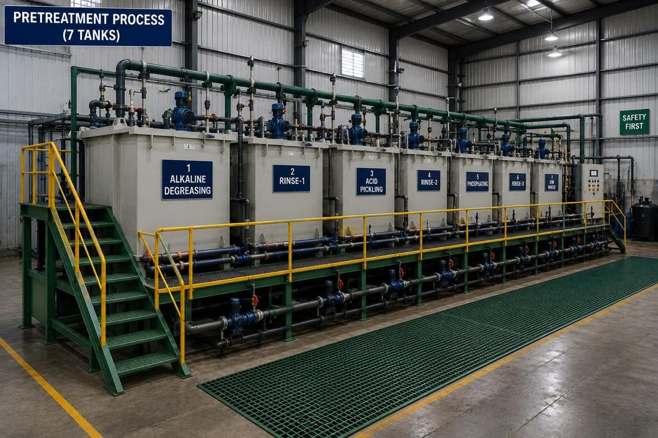
Ganesh runs a seven-tank pretreatment line, a 16 ft × 16 ft shot blast chamber, an 18 ft × 14 ft electrostatic powder booth, a wet paint booth and a curing oven. Film thickness is checked with a DFT gauge and adhesion with a cross-hatch test, which are the two measurements that answer most finish complaints.
The paint shop capability describes the line, and the shot blasting capability the chamber. The pretreatment sequence is where most coating failures begin, not at the booth: a panel that enters the powder booth with residual drawing oil or a partly converted surface will pass a thickness check and fail a cross-hatch test three weeks later. The seven-tank pretreatment process sets out the tank sequence and what each stage removes.
Where a part is welded before coating, the finish callout has to reach the weld. Spatter on a visible face is a surface defect, not a weld defect, and no amount of powder hides it. The outdoor enclosure failure guide covers the combination of edge coverage, pretreatment and film build that decides whether a coated panel survives a monsoon season.
What to put on the drawing
- Standard reference. ISO 21920-1 in the general notes, not ISO 1302.
- Parameter, value and cut-off on any machined or ground face, written as a complete specification operator.
- No Ra on cut edges. Replace it with a burr limit, a dross limit and a boundary sample for visible faces.
- Corrosivity category to ISO 12944-2, then the DFT range and the measurement standard, ISO 19840.
- Blast cleanliness and profile as separate callouts, Sa 2½ and medium 40–70 µm.
- Adhesion class and the test standard, ISO 2409, with the sampling frequency.
- Faces that must not be coated, identified by view: threads, earth points, guide shoe faces and mating surfaces.
- Colour and gloss by a reference sample or a RAL number, not by a photograph.
The quotation request takes the drawing and the finish specification together; the two most common gaps in a pack are the corrosivity category and the masking list.
When a finish symbol is the wrong control
A finish symbol cannot specify colour, gloss, hiding power or UV stability, and it cannot specify that a coated part will survive a salt spray test. Those need a coating system specification and a test method. A Ra value also cannot specify a surface that will be anodised or electroplated, because those processes add their own preparation and their own surface condition.
Ganesh does not machine, grind, anodise or electroplate. Where a drawing needs a ground face, a lapped seal or an anodised finish, that operation sits outside this route and needs a different supplier in the chain. Saying so before the order is placed is cheaper than a first article that fails on a surface the shop was never equipped to produce.
Send the drawing with the surface and coating notes, the corrosivity category and the masking list. The engineering team will return the callouts the line can measure, and the ones that need a different process.
Frequently asked questions
Is Ra 1.6 achievable on a laser-cut edge?
The edge measures about Ra 2–5 µm on 2 mm CRCA, but the more useful answer is that the callout is not measurable: Ra 1.6 needs a 0.8 mm cut-off and 4 mm of evaluation length, and the edge is 2 mm wide. Call out deburring and freedom from dross instead.
Which standard replaced ISO 1302?
ISO 21920-1:2021 covers the indication of surface texture on drawings, with ISO 21920-2 for parameters and ISO 21920-3 for specification operators. ISO 1302:2002, ISO 4287 and ISO 4288 were withdrawn, so update the general notes.
What coating thickness should I specify for outdoor steel?
Match the system to the corrosivity category in ISO 12944-2: about 60–120 µm for C3, 120–180 µm for C4 and 180–250 µm for C5. State the category and the test method, because a thickness measured over a blasted surface reads high without the ISO 19840 correction.
How is adhesion tested on a powder-coated panel?
By cross-cut to ISO 2409: six cuts each way, 1 mm spacing below 60 µm, 2 mm from 60 to 120 µm and 3 mm above 120 µm, then tape pull and classification from 0 to 5. Class 0 to 1 is the usual acceptance on production parts.
Do I need a surface finish symbol on a painted part?
Usually not. The paint hides the substrate, so Ra on the steel is not the requirement. Specify blast cleanliness, profile, dry film thickness, adhesion and colour instead, and keep Ra for machined pads, bores and sealing faces.
Sources and further reading
- ISO 21920-1:2021 — Geometrical product specifications (GPS) — Surface texture: Profile — Part 1: Indication of surface texture · reviewed 3 Nov 2026
- ISO 12944-5:2019 — Paints and varnishes — Corrosion protection of steel structures by protective paint systems — Part 5: Protective paint systems · reviewed 3 Nov 2026
- ISO 2409:2020 — Paints and varnishes — Cross-cut test · reviewed 3 Nov 2026
Have a finish callout you are not sure about?
Send the drawing with the surface and coating notes. Our coating team checks the blast, pretreatment and film thickness against the standard you cite, and returns the callouts the line can verify.
Request a quote