Key takeaways
- A 100 kVA set moves about 2.0 m³/s of cooling air, so the louvre free area must be at least 0.67 m² to keep face velocity under 3 m/s; above 4 m/s rain carry-over into the radiator rises sharply.
- Design the canopy for 1.2 kPa wind pressure (IS 875 Part 3, 44 m/s basic speed), which is 3.2 kN on a 2.4 × 1.1 m side panel and 158 N per fixing across 20 screws.
- Keep the fuel fill neck at 1.0 m above the plinth and the drip tray at 5 L minimum; a fill point above 1.5 m is where jerry-can spills and site shutdowns start.
- Two 8 mm drain holes per base rail and a 60–80 µm powder film with masked pads prevent the two corrosion paths that write off a canopy in three monsoons.
- Set door gaps at 3 ±1 mm with gasket compression of 25–35%, and fit three hinges above 900 mm door width, or the latch corner loses seal within a season.
A canopy on a factory wall gets looked at every day. The same canopy on a telecom site, a mine pump house or a highway substation is visited once a quarter, and the failure that matters is the one nobody sees until the set refuses to start. Power plant enclosure design for those sites is a different exercise from designing for a plant room: there is no drain, no compressed air, no fitter with a grinder, and the weather arrives sideways.
The numbers are unforgiving. A 100 kVA set rejects roughly 30 kW of heat to the cooling air, which means about 2.0 m³/s through the radiator. Push that through a louvre with too little free area and the air-on temperature rises 5–8 °C, the set derates, and the first symptom the operator reports is "it cuts out in summer". Size the same opening for 3 m/s face velocity and the canopy survives a 50 mm/h monsoon without pulling water into the core.
This guide covers the six failures that account for most remote-site canopy callouts — rain carry-over, fuel access, base corrosion, door seal loss, lifting damage and fixing fatigue — with the wind, rain and thermal numbers behind each, and the drawing callouts that close them before the first cut. It is written for the manufacturing engineer who has to defend the design in a quotation review, not for a brochure.
What fails first in a remote-site power plant enclosure design?
Water, then fuel access, then the base. Electrical and acoustic faults are rarer, and they usually start as one of those three.
Rain enters a canopy by three routes: louvre carry-over, gaps at the door line, and capillary travel along fixings and seams. The louvre is the big one and it is a velocity problem. Water droplets in an airstream follow the air until the velocity drops or the direction changes sharply enough for inertia to carry them onto a surface. A 45° blade at 50 mm pitch is a direction change. At 2 m/s the droplet hits the blade and drains. At 5 m/s it is carried past the blade tip and into the plenum.
So the free area is set by the airflow, not by the physical size of the opening. For a 100 kVA set drawing 2.0 m³/s, a 3 m/s limit gives 0.67 m² of free area. The louvre that delivers 0.67 m² of free area at 40% usable free area is 1.7 m² of physical opening. That is a 1,700 × 1,000 mm bank, not the 900 × 600 mm panel that often gets drawn.
Wind pressure is the second load. IS 875 (Part 3) gives a basic wind speed of 44 m/s for Mumbai and 39 m/s for Nagpur, and the design pressure is q = 0.6 V². At 44 m/s that is 0.6 × 44² = 1,162 N/m², so use 1.2 kPa. A 2,400 × 1,100 mm side panel is 2.64 m² and takes 3.17 kN. Across 20 fixings that is 158 N each, which an M6 self-drilling screw in 1.6 mm steel handles with a large margin — provided the screws are there and the panel has a stiffener so it does not oil-can between them.
Dimensions, clearances and the limits that decide service
The table is the specification sheet for a 40–125 kVA remote-site canopy. Values in the middle column are what a site needs; the right column is what the fabrication route can hold.
| Parameter | Typical value for a remote site | Ganesh limit or note |
|---|---|---|
| Canopy skin | 1.6–2.0 mm CRCA to IS 513 | 0.8–40 mm custom range; 12 kW laser cuts full panel sets on a 40 ft × 16 ft bed |
| Base frame | 100 × 50 × 5 mm channel, or 3.0 mm formed section to 125 kVA | Formed on the 200 T, 5-axis brake with a 4,450 mm bed; jig-welded |
| Louvre free area | ≥ 0.67 m² for 2.0 m³/s at 3 m/s | Opening set at 1.5 × radiator face area; 40% usable free area assumed |
| Louvre blade | 1.2–1.5 mm, 45°, 50 mm pitch | Laser cut and form-tooled; pitch held to ±0.3 mm |
| Door width before a third hinge | 900 mm | Three hinges and a double return above 900 mm |
| Door gap and gasket | 3 ±1 mm, 25–35% compression | Feeler gauge at four points per door |
| Fuel fill height | 1.0 m above plinth | Drip tray 5 L minimum under the fill neck |
| Base drain holes | 2 × 8 mm per rail at the low end | Drilled before coating; coated inside where the gun reaches |
| Lifting points | 4-point lift with spreader, SWL 2 × assembly weight | Set by the centre of gravity, not by the panel centres |
| Envelope tolerance | ±2.0 mm overall | ISO 13920 class B on the welded frame; ±0.5 mm on sheet features |
| Coating | 60–80 µm powder over seven-tank pretreatment | DFT at five points per panel, including one cut edge |
| Earthing | M8 stud, < 0.1 Ω to the base frame | Masked before the booth |
Two of those rows are worth arguing about at the quotation stage. The first is the louvre area, because it is the row that most often gets value-engineered down to fit a standard panel size. The second is the lifting arrangement, because a canopy lifted on four eyebolts placed at the panel corners rather than over the centre of gravity will rotate, land on one edge, and arrive with a twisted base frame that no amount of door adjustment can fix.
Six failure modes, in the order they appear
Rain carry-over at the discharge bank
The discharge louvre faces the weather on most sites because the radiator has to face away from the building. Water that passes the blades lands on the core, and a wet core loses perhaps 10–15% of its heat rejection until it dries. Repeated wetting carries dust into the fins and starts corrosion at the tube-to-fin joint.
The fixes are geometric. Add a rain hood with a 150 mm overhang and a drip lip, or use a double-bank louvre with a 100 mm air gap between banks so the second bank catches what the first passes. A drift eliminator adds pressure drop, which costs fan power, so it is the last resort rather than the first.
Fuel fill that the operator cannot reach
Fuel access is a human-factors problem that becomes an engineering problem. A fill neck on the roof or high on a side panel means the operator lifts a 20 L can to shoulder height, braces it on the enclosure, and pours. Spilled diesel runs down the panel, softens the powder at the seam, and collects in the base channel.
Put the fill at 1.0 m, behind a lockable door that opens 100° or more, with a 5 L drip tray under the neck and a lip on the tray. The fill hose route inside the canopy needs a 150 mm bend radius so it does not kink when the door is closed on it. If the set uses a base tank, the fill is part of the tank design and the canopy only provides the access aperture — the two drawings have to agree on centrelines before either is released.
Corrosion from the inside of the base
A closed channel holds condensation. On a site with a 15 °C day–night swing, a 2.4 m rail condenses a film of water on its inner top face every morning, and that water runs to the low end. With no drain, it sits against bare steel and the rail rusts from the inside out. The outside still looks painted when the section has lost half its wall.
Two 8 mm holes per rail at the low end, drilled before coating, plus internal coating where the gun reaches, is the whole fix. It costs a drill operation and it is the difference between a ten-year frame and a four-year frame.
Door sag and gasket set
A canopy door is a large flat panel on two hinges with a gasket applying a continuous load. At 900 mm wide and 1,600 mm high in 1.6 mm steel, the door bows 3–5 mm at mid-height, the gasket compresses at the latch and barely touches at the hinge, and the seal takes a permanent set within a season.
Three details prevent it: a 20 mm return on all four edges, a horizontal stiffener at mid-height, and a third hinge once the door passes 900 mm. The hinge axis matters too. It must sit so the gasket compresses before the door face contacts the frame, otherwise the door hangs on the gasket rather than on the hinge.
Lifting and transport damage
A canopy is lifted onto a truck, off a truck, and onto a plinth, usually with whatever slings the site has. Design for a four-point lift with a spreader beam, mark the lifting points on the drawing, and put the SWL at twice the assembly weight. The centre of gravity moves when the set is installed, so the lifting points belong on the base frame, not on the canopy skin.
Road transport is a fatigue load, not a static one. A 400 km journey at Indian road frequencies loads the door hinges and the panel fixings several thousand times. Anything that is going to fatigue loose — a hinge screw into 1.6 mm steel, an unbonded stiffener — will be loose on arrival. Use rivet nuts or weld the stiffener, not self-tapping screws into a single wall.
Fixing fatigue and panel drumming
Panels fixed only at their edges drum at the engine firing frequency. The skin does not need to resonate to be a problem; a 1.2 × 1.0 m panel in 1.6 mm steel has a first bending mode around 6 Hz, well below the 50 Hz firing frequency of a 1,500 rpm four-cylinder set, so the response is mass-controlled and the panel moves as a diaphragm. Stiffeners at 600 mm centres raise the mode and cut the movement.
The fixings themselves see that movement. A screw in a clearance hole wears the hole, the joint loosens, and the panel starts to rattle. Use a stiffener bonded or welded to the skin, and keep fixings at 150 mm pitch on the door and 200 mm on the panels.
What Ganesh actually runs
Panels are nested and cut on the 12 kW fibre laser with the 40 ft × 16 ft bed, so a canopy side, its door and its louvre blanks come off one sheet and match in thickness and flatness. Forming runs on the 200 T, 5-axis brake with the 4,450 mm bed and Delem control, which forms a 2,400 mm return in a single hit and keeps the door aperture square. The forming behaviour of those long returns is covered in bending for genset canopies and panels. Base frames and internal baffles are welded on three CLOOS robotic MIG cells or at the 30+ manual stations, on fixtures designed in our tool room.
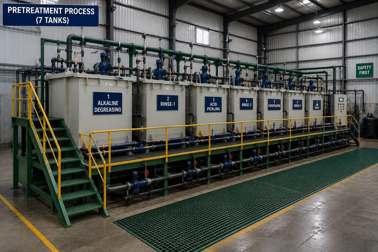
Coating goes through seven-tank pretreatment, the 16 ft × 16 ft shot blast chamber where the section warrants it, the 18 ft × 14 ft powder booth and the curing oven, with DFT and cross-hatch checks per batch. Canopies and base frames for Mahindra Powerol programmes have run this route, and the genset parts page lists the inputs that let us quote without a second round of questions.
We do not run the acoustic or weather test. The dB(A) figure and the IP rating are proved on the assembled unit by the OEM or a third-party laboratory. Our job is to build the drawing that was designed against those figures, and to say when the drawing will not get there.
What to put on the drawing
- Site data — basic wind speed, rainfall intensity, ambient temperature range and whether the site is coastal. Coastal means a coating system decision, not a thicker panel.
- Airflow — radiator core face area, fan volumetric flow and the maximum acceptable air-on rise. This sizes the louvre.
- Fuel arrangement — tank capacity, fill neck height and side, drip tray volume, and whether the fill is on the canopy or the tank.
- Lifting — assembly weight, centre of gravity, lifting point positions and the spreader requirement.
- Door schedule — width, height, hinge side, gasket type and compression range, and the stay or hold-open detail.
- Drainage — drain hole size, position and the fall on the base rails.
- Coating — system, DFT range, masked faces, and the touch-up procedure for site damage.
- Tolerance split — ISO 13920 class B for the welded frame, ISO 2768-1 class m for formed features, and any tighter callout written explicitly rather than inherited.
The tolerance split is the callout that prevents the most disputes. A welded 2,400 mm frame under ISO 13920 class B is allowed ±6 mm on that dimension, while the formed door panel under ISO 2768-1 class m in the 2,000–4,000 mm band is allowed ±2 mm. If the drawing asks for ±2 mm on the assembled envelope without saying so, the quote either carries an unnecessary fixture or the first article fails on a dimension nobody agreed.
When a fabricated canopy is the wrong route
Three cases. A canopy for a set above roughly 500 kVA is usually a container-type enclosure with a structural steel frame and a different transport envelope; that is heavy fabrication, not sheet metal. A site that needs a walk-in plant room with a concrete plinth and fire separation is a building, and the enclosure is only the cladding. And a coastal site with a salt-laden atmosphere may need a duplex stainless or aluminium skin, which changes the welding and coating route rather than the panel gauge.
For the rest, the canopy is a sealed steel box with a louvre that respects velocity and a base that drains. The genset canopy hub collects the related guides on frames, doors and louvres, and the canopy frame manufacturing guide covers the welded structure at the centre of it. If the design is settled, send the drawing with the site data through request a quote and we will review the route before pricing.
Frequently asked questions
How much louvre free area does a remote-site genset canopy need?
Size the free area for a face velocity of 3 m/s or less. A 100 kVA set moves about 2.0 m³/s, so the free area is 2.0 / 3 = 0.67 m², and the physical louvre is roughly twice that once blade angle and rain defence are counted.
Why does rain get into my canopy even with louvres?
Because free area was sized on the opening, not on velocity. Above about 4 m/s through the free area, wind-driven rain strips off the blades and travels with the air into the radiator. A rain hood, a double bank or a drift eliminator fixes it; a steeper blade does not.
What height should the fuel fill point be?
About 1.0 m above the plinth. That is a comfortable lift for a 20 L container and keeps the fill hose short. Above 1.5 m the operator stands the can on the enclosure, and that is where spills and dents happen.
How many hinges does a canopy access door need?
Two hinges up to 900 mm door width, three above it, with the third at mid-height and a double return on the free edges. A 900 × 1,600 mm door in 1.6 mm steel bows 3–5 mm under gasket load without the return.
Can a fabricated canopy hold IP54?
The enclosure can carry IP54 sealing features — gasketed doors, gland plates, sealed penetrations — but the rating applies to the assembled enclosure, not to an individual panel. Specify the rating and the test method, and test the assembled unit rather than a sample door.
Sources and further reading
- IS 875 (Part 3) — Wind loads on buildings and structures · reviewed 3 Nov 2026
- CPCB — Noise limits for diesel generator sets · reviewed 3 Nov 2026
- ISO 2768-1 — General tolerances for linear and angular dimensions · reviewed 3 Nov 2026
Send the site conditions with the drawing
Share the enclosure drawing, the genset rating, the wind and rainfall data for the site and the annual quantity. We review louvre area, fill access and the coating route before quotation.
Request a quote