Key takeaways
- Silicone is the only plug material that survives a powder cure at 180–200 °C without taking a set; EPDM is rated near 150 °C and neoprene near 120 °C, both below the oven.
- A plug needs 5–10% interference on the hole diameter: about 0.3–0.8 mm on a 6–12 mm hole, less and powder finds the gap, more and the plug splits or will not seat.
- Air in a blind hole expands 1.55 times between 25 °C and 190 °C, so an unvented plug is pushed out unless it is slit or the hole is vented.
- Fitting and removing a plug takes 6–9 seconds and 4–6 seconds; a panel with 30 masked features carries 5–7.5 minutes of handling on every piece.
A plug that seats at the bench can be missing when the part leaves the oven. The air sealed inside a blind M8 hole expands from 1.0 to 1.55 times its volume between 25 °C and 190 °C, and that pressure pushes an unvented plug out of the bore before the powder gels. The thread comes out at 70 µm instead of 0 µm, the bolt starts two turns and stops, and the panel is a rework ticket.
Masking plugs and caps are bought by the thousand and specified by almost nobody. That is the gap this page closes: which material survives the cure, how much interference the hole needs, how the plug is vented, and how you kit, count and retire them on a line that runs hundreds of parts a week.
The rule fits in one line. Silicone for anything that passes through the cure oven, tape for flat faces that never see a bore, and a vented plug wherever the hole is blind.
Which plug material survives a 190 °C cure?
Silicone, and only silicone, for parts that go through a powder cure at 180–200 °C for 10–20 minutes. EPDM is rated near 150 °C and neoprene near 120 °C, and both soften well before the oven reaches set temperature.
Silicone wins for two reasons that matter in a booth rather than a catalogue. Its service temperature is 260 °C continuous, so the cure is a comfortable margin rather than a limit. Its thermal expansion is also roughly twenty times that of steel, about 2.5 × 10⁻⁴ per K against 1.2 × 10⁻⁵ per K, so a silicone plug grips harder at 190 °C than it did at 25 °C.
That second property is the one nobody specifies and everybody depends on. A silicone plug that felt loose in a cold hole tightens by around 4% in linear size across the cure, which closes a gap that powder, at 30–50 µm per particle, would otherwise pass through.
Neoprene and EPDM plugs are not useless. They are the right answer for a wet-paint line that air-dries at 60–80 °C, for masking during blasting, and for plugs that hold a part during handling. They are the wrong answer for a curing oven, and the failure is quiet: the plug comes out looking fine and will not stay in on the second cycle.
What the plug is actually sealing
A plug does three jobs and only the first is obvious. It stops powder entering the bore. It keeps the bore wall free of film so a fastener engages over its full thread length. And on a mating face it preserves the datum, because two coated surfaces add 0.12–0.16 mm to a stack-up that may only have 0.2 mm of allowance.
Powder is not a liquid that creeps. It is charged particles sprayed at 60–100 kV, and they wrap a grounded edge. That wrap is why a plug needs a flange: the flange shields the annulus around the hole, where the film would otherwise bridge onto the bore lip and chip when the fastener is driven.
A plug with no flange will hold the bore and lose the lip. On an M8 hole, the lip is 1 mm wide, and a chip there is exactly where a bolt head seats.
Masking plugs and caps by size, temperature and use
The table below is the working set for a powder line curing at 180–200 °C. Sizes are the plug's outside diameter at the sealing land, not the hole it is sold for, because a 10 mm plug commonly serves a 9.5–10.5 mm hole.
| Plug type | Size range | Service temperature | Where it belongs | Ganesh limit or note |
|---|---|---|---|---|
| Tapered silicone plug, flanged | 3–50 mm | 260 °C continuous | Blind and through holes, threads | Fitted between dry-off and booth |
| Silicone pull plug with tab | 5–25 mm | 260 °C | Holes that must be pulled from the back | Tab must sit outside the spray path |
| Slit or vented silicone plug | 6–30 mm | 260 °C | Blind holes deeper than 1.5 × diameter | Prevents the oven blow-out |
| Silicone stud cap, female | M3–M20 | 260 °C | Male threads, earth studs | Flange must cover the stud root |
| Silicone cap, push-on | 4–40 mm | 260 °C | External bosses and pins | Loses grip above 40 mm |
| EPDM cap | 4–30 mm | 150 °C | Wet paint, air dry, blasting | Not for a 180 °C cure |
| Neoprene plug | 3–20 mm | 120 °C | Handling and transit only | Softens and marks at cure |
| Polyester high-temp tape disc | 10–100 mm | 200 °C | Flat mating faces, earth pads | Die-cut, one use per cure |
| PTFE solid plug | 4–20 mm | 260 °C | Chemical resistance, odd bores | No interference, needs a retainer |
Two rows decide most arguments. The first is the vented plug: any blind hole deeper than 1.5 times its diameter traps enough air to displace an unvented plug. The second is the tape disc, which is the only practical mask for a flat datum face wider than about 40 mm, where a moulded plug becomes a bespoke part.
Colour coding is not cosmetic at scale. A line that stocks five silicone sizes in five colours can be audited by eye from two metres away, and a wrong-size plug shows up as a colour in the wrong hole rather than as a coated thread three weeks later.
How much interference does the hole need?
Five to ten per cent of the hole diameter. A 6 mm hole takes a plug 6.3–6.6 mm across the land, a 12 mm hole takes 12.6–13.2 mm, and a 20 mm hole takes 21–22 mm. Below 5% the plug seals on the burr and nothing else; above 10% it will not seat by hand and the operator either forces it or leaves it out.
The hole matters as much as the plug. A punched hole is not round, not cylindrical and not the size on the drawing. It carries a taper of 0.1–0.3 mm through the thickness on 3 mm sheet, a rollover at entry and a burr at exit, and the plug seats on the smallest section it meets. That is why the plug is sized to the hole's entry diameter, not its nominal.
A laser-cut hole is closer to nominal, typically within 0.1–0.2 mm on 2–3 mm sheet, and a reamed or bored hole is closer still. On a precision bore the interference rule changes: a 0.5 mm oversize plug in an H8 bore distorts the bore wall or splits at the slit, and a tape disc over the face is the better mask.
The sizing chart that stops the argument
Standardise on a 2 mm step from 4 to 20 mm and a 5 mm step above that. Five sizes then cover roughly 80% of the features on a typical enclosure: 8, 10, 12, 16 and 20 mm. Anything between those is a special order that arrives in three weeks and gets substituted on the floor.
Where the drawing gives a hole tolerance, quote the plug against the maximum hole size. A 10 mm hole with an H12 tolerance runs to 10.15 mm, so a 10.6 mm plug has 0.45 mm of interference at worst case and 0.6 mm at best. That 0.15 mm spread is the difference between a plug that seats with a thumb and one that needs a press.
Threads are a separate problem
An internal thread is not a plain bore. The plug must enter the minor diameter and seal on the flanks without cutting into the crest. For M6, M8, M10 and M12 coarse threads the basic minor diameters are 4.917, 6.647, 8.376 and 10.106 mm, so a thread plug is sized to the minor diameter plus 5–8%, not to the nominal thread size.
A plug sized to the nominal diameter will not enter at all. A plug sized to the minor diameter with no interference will fall out. The difference between those two failures is 0.4 mm on an M8, which is why thread plugs come in thread sizes rather than millimetres.
Protecting threads, holes and faces at scale
At one part a week, masking is a detail. At 200 parts a week it is a line operation with its own kitting, counting and scrap rate, and those numbers change what the design should be.
Handling time is fixed per feature. A tapered plug takes 6–9 seconds to fit and 4–6 seconds to remove. A stud cap is quicker, 3–5 seconds each way, because it pushes onto a male thread rather than into a bore. A die-cut tape disc on a 50 mm datum face takes 20–30 seconds each way, including the rub-down that makes it stay.
Thirty masked features on one enclosure is therefore 5–7.5 minutes of fitting and removal per piece. On a 50-piece batch that is 4–6 hours of labour that does not appear in powder consumption, oven cycle or booth time. It is the first number to put in front of a designer who has specified masking on every hole.
Kit by part, not by size
The failure at scale is not the wrong plug. It is the missing plug. A bin of mixed sizes at the booth means the operator picks by eye, and eye is wrong at 8 mm against 10 mm under a coat of powder dust.
Kit the plugs for one part number into one bag, with the count on the bag and the mask positions marked on the shop card. A panel with 12 plugs gets a bag of 13, one spare, reconciled at the end of the batch. The spare is not generosity; it is the cheapest way to stop a line waiting on a consumable worth less than a rupee.
Three rules make kitting work:
- One bag per part number per batch, counted and labelled with the drawing revision.
- Count in equals count out, with the difference written on the batch card, not investigated after dispatch.
- Plugs that come back with powder on the shank go to cleaning, not back into the bag.
Retire plugs on evidence, not on looks
A silicone plug lasts 20–50 cure cycles. It fails in sequence: the flange takes a set, the shank polishes smooth, then the plug holds by friction alone and drops out at the spray gun or in the oven.
Retire a plug when it will not hold in a clean test hole of its nominal size, when the shank carries a visible powder film, or when the flange has torn at the slit. A plug that has been through 30 cycles has taken 30 passes at 190 °C, and its compression set is permanent. Cleaning restores the surface, not the shape.
Powder on the shank is worse than dirt. It is 60–80 µm of cured polyester on the sealing land, more than the interference on a small plug, and it cannot be seen at arm's length on a dusty bench.
Caps for studs and male threads
Male threads and earth studs are easier to protect than bores and harder to protect well. A push-on cap covers the thread but not the root, and the root is where powder bridges to the stud and where a star washer needs bare metal.
Use a cap with a flange that seats on the panel face, not a plain tube. The flange keeps film off the 3–5 mm annulus around the stud root, which is the contact area for the bonding washer. On an earth stud, that annulus is the difference between a 0.1 Ω bond and a megohm reading.
For studs longer than 15 mm, a cap covering only the first 10 mm leaves the rest coated, and a nut run down the thread will not pass. Either cap the full length or specify a chase after coating, and write which one on the drawing.
What Ganesh actually runs
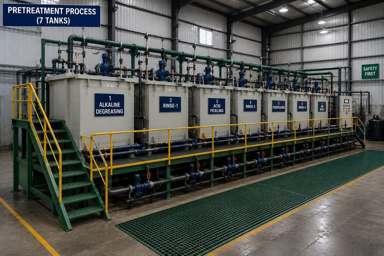
Coated work goes through the seven-tank line, dry-off, then the 18 ft × 14 ft electrostatic powder booth or the wet paint booth, then the curing oven. Film is checked with a DFT gauge and adhesion with a cross-hatch test. Masking is done by hand between dry-off and the booth, in silicone, against a mask schedule transferred from the drawing to a shop card for each batch.
A 2,400 mm panel masks differently from a 200 mm bracket. On long panels the plugs are fitted with the panel flat, before it is racked, because reaching a mask on a vertical 2.4 m panel means leaning on freshly prepared steel. The booth takes the 18 ft × 14 ft envelope, so a long canopy side is masked and sprayed without a joint.
Parts for Godrej & Boyce and TKE run through this line, including enclosures where the bonding test is part of the first article. The data centre rack product page shows the panel type where earth studs, cable entries and thread masking meet on one part, and the paint shop page lists the line.
What to put on the drawing
- A mask table: feature, plug or cap size, quantity per part, and whether the mask is removed before dispatch.
- The thread callout with the class after coating, for example M8-6H after chase, so the shop knows whether to mask or chase.
- Earth stud locations and the test value: 0.1 Ω maximum between stud and enclosure body, measured on the first article.
- A note on blind holes: "vent or slit mask permitted" if the drawing allows it, because the alternative is a bespoke vented plug.
- Whether the masked area may carry conversion coating. A thin phosphate is acceptable under a star washer and not acceptable on a sliding face.
- The film specification and measurement points per ISO 2808, so the mask boundary can be inspected against a number.
If the part is destined for a C4 or C5 environment under ISO 12944-2, add the post-coating treatment at each mask: a sealed stainless stud and washer, or a zinc-rich touch-up at the boundary. A bare pad in a wet enclosure is a corrosion site, and no plug prevents that.
When a plug is the wrong answer
Masking is a manual operation defending a coating that should not be on the feature. Four cases where the design should change instead.
Threads that will be chased anyway. If the assembly uses a tap or a thread-forming screw, coat the thread and chase it. Masking and then chasing is two operations for one result, and the mask can fall out between them.
Large flat areas. Above about 50 mm across, a moulded plug becomes a bespoke part with a lead time. Coat the face and fit the plate, gasket or label over the film, or mask with tape if the area truly must stay bare.
Features that can be added after cure. Rivet nuts, clinch nuts and standoffs can be installed in a coated hole where the joint allows. A blind rivet nut is a defined operation with a known pull-out; a masked thread is a plug that can go missing.
C5 and immersion service. A bare earth pad in a C5 enclosure passes the bond test and corrodes in service. The answer is a sealed connection or an external bonding strap, not a bigger mask.
We do not laser-ablate coating or brush-plate a masked area. If a part needs a conductive path that cannot be masked, the route is a different coating system or a mechanical bond, and it is better to say so before the drawing is frozen.
Send the drawing with the earth studs, thread callouts and mating faces marked to request a quote. The mask schedule is reviewed with the coating route, so plug cost and handling are priced with the film rather than discovered at first article. The coating and surface treatment hub indexes the rest of the preparation and finish guides.
Related reading: the Coastal site corrosion: design, failure modes and the fix and the Degreasing aluminium parts before coating take the same problem further.
Frequently asked questions
What temperature do masking plugs need to withstand for powder coating?
At least 200 °C, and 260 °C continuous is the practical specification. Powder cures at 180–200 °C for 10–20 minutes, and a plug that softens at 180 °C takes a compression set on the first cycle, then falls out on the second. Silicone covers this; EPDM at 150 °C and neoprene at 120 °C do not.
How much bigger should a masking plug be than the hole?
Five to ten per cent of the hole diameter, so 0.3–0.8 mm on a 6–12 mm hole and 1.0–1.5 mm on a 20 mm hole. Below 5% the plug seals on the burr only and powder migrates past it. Above 10% the plug is hard to seat, sits proud of the face and can be dislodged by the spray gun.
Can I reuse silicone masking plugs?
Yes, typically for 20–50 cure cycles. Retire a plug when it no longer holds by friction in a clean test hole, when the shank carries cured powder, or when the flange has torn. Powder on the shank is the common cause of a plug that fits at the bench and leaks at the booth, because the film stops the silicone touching steel.
Why do my plugs fall out in the oven?
Trapped air. A blind M8 hole holds about 0.4 cm³ of air at 25 °C, and at 190 °C that air occupies 1.55 times the volume. If the plug seals the bore completely, pressure builds behind it and pushes it out before the powder gels. Use a slit or vented plug, or drill a 1 mm vent that the drawing permits.
Should masking plugs go on before or after pretreatment?
After pretreatment and dry-off, immediately before the booth. A plug fitted before the seven-tank line holds rinse chemistry against bare steel, and the part leaves the dry-off oven with rust bloom or a blister ring around the mask. The plug also carries the chemistry into the next tank.
Sources and further reading
- ISO 2808:2019 — Paints and varnishes: determination of film thickness, the method behind the DFT readings on a coated part · reviewed 3 Nov 2026
- IEC 61439-1:2020 — Low-voltage switchgear and controlgear assemblies: general rules, including the 0.1 Ω protective circuit requirement · reviewed 3 Nov 2026
- ISO 12944-2:2017 — Corrosion protection of steel structures: classification of environments, C1 to C5 · reviewed 3 Nov 2026
Send the drawing with the features that must stay bare
Mark the earth studs, threaded holes and mating faces. We will confirm the plug sizes, the interference on each hole, and the handling the masking adds to the piece.
Request a quote