Key takeaways
- Design the cover from three datums only — hinge axis, latch striker and counterweight silhouette — and hold the hinge axis to ±0.5 mm; everything else can move 1.5 mm without a fit problem.
- In 2.0 mm CRCA a 90° bend takes an inside radius of 2.0 mm minimum, but a visible outer crown needs 40–80 mm so the panel does not oil-can between weld spots.
- Spot-weld pitch on 1.6–2.0 mm cover panels should stay at 25–40 mm with 8 mm edge distance; wider pitch plus an unsupported flat over 300 mm is the usual cause of a 1–2 mm drumming panel.
- Powder at 60–80 µm over a seven-tank pretreatment survives yard exposure only if the laser-cut edge and the weld seam under the hinge are coated; edge coverage is the first failure point, not the face.
- A 1,240 × 900 mm blank in 2.0 mm CRCA weighs 17.5 kg — check it with the weight calculator before quoting, because labour and coating follow the mass.
A counterweight cover fails in the field for one of two reasons, and neither is the steel grade. Either the hinge axis drifts far enough that the panel binds on the cab and the operator leaves it unlatched, or the coating breaks at the latch striker and rust runs down the rear face within one monsoon. Forklift counterweight cover manufacturing is judged on those two outcomes, and both are decided long before the first blank is cut.
This walk-through follows a cover for a 2.5–3.5 t counterbalance truck: a wrap-around panel roughly 1,150–1,300 mm wide, 450–550 mm high, formed from 1.6–2.0 mm CRCA with a crowned top, a hinge line at the cab end, a latch striker at the rear and two or three stiffener beads across the flat. The route is laser blank, brake-form the crown and returns, fixture-weld the hinge and latch reinforcement, seven-tank pretreatment, powder coat, fixture check. Every step has one number that decides whether the part is good, and those numbers are below.
For the wider set of tractor and material handling parts we build, the tractor, forklift and material handling hub collects the related guides.
Which three dimensions actually decide whether the cover fits?
The hinge axis, the latch striker face and the clearance to the cast counterweight decide fit. Every other dimension on the drawing can move 1.5 mm and the operator will not notice; move the hinge axis by 1.5 mm and the cover will not close without a lift at the rear corner.
Counterweights are castings, and a cast SG iron counterweight on this class of truck typically carries ±2–3 mm on as-cast surfaces, ±0.5 mm where faces are machined. A cover drawn tight to the nominal casting will interfere on roughly half the trucks it meets. Draw 6–8 mm of clearance to the casting silhouette and control the two datums instead.
The hinge is a pair of welded-on leaves with a pin, or a piano hinge on longer covers. In production the leaves are located by a pin through the fixture, not by the hole in the sheet, because a laser-cut hole in 2.0 mm sheet can sit 0.3 mm off the datum while the pin position is what the truck feels.
Material and thickness: what the cover needs
IS 513 grade D is the default for a formed cover: it is a drawing-quality cold reduced sheet with enough ductility to take a 40–80 mm crown without splitting, and it takes a zinc phosphate conversion coat predictably. Grade DD is used where the crown is deeper than 60 mm over a short run or where the panel is drawn rather than bent. Hot rolled IS 2062 E250 at 2.5–3.0 mm appears on heavier truck covers and on the reinforcement plates that carry the hinge.
Thickness is a stiffness argument, not a strength argument. Deflection of a flat panel under a point load falls with the cube of thickness, so 2.0 mm is roughly twice as stiff as 1.6 mm for the same span. That is why a 1.6 mm cover needs a bead or a return every 250–300 mm of unsupported width while a 2.0 mm cover can carry 350–400 mm.
| Parameter | Typical value for a 2.5–3.5 t truck cover | Ganesh limit or note |
|---|---|---|
| Cover skin thickness | 1.6–2.0 mm CRCA, IS 513 grade D | 0.8–40 mm range for custom parts; 2.0 mm is the most common cover gauge |
| Reinforcement plate | 2.5–3.0 mm IS 2062 E250 | Laser cut to 20 mm; 30–40 mm plate work is done on the iron worker |
| Inside bend radius, wrap bends | 1.0 × t minimum (2.0 mm at t = 2.0) | 200 T, 5-axis brake with a 4,450 mm bed forms the full cover in one handling |
| Crown radius, visible top | 40–80 mm | Radius punch set; hold with a radius gauge, not a sample part |
| Hole-to-bend distance | ≥ 2.5 t + R (7 mm at t = 2, R = 2) | Design 10 mm; closer holes distort during forming |
| Minimum flange for a 90° bend | 4 t to 5 t (8–10 mm at t = 2) | With a 16 mm V-die, 12 mm is the practical minimum on the brake |
| Spot weld pitch on 2.0 mm skin | 25–40 mm, 8 mm minimum edge distance | 30+ manual spot stations; robotic MIG cells for reinforcement plates |
| Overall cover dimension | ±1.5 mm | ±0.5 mm typical sheet metal tolerance; tighter only on named features by agreement |
| Hinge pin position | ±0.5 mm from datum | Fixture-located and checked with a pin gauge on the checking fixture |
| Powder coating thickness | 60–80 µm | Measured with a DFT gauge on every batch |
| Coating adhesion | Cross-hatch ISO 2409 Gt0–Gt1 | Cross-hatch test in-house; salt spray per ASTM B117 sent to a test laboratory |
Forming the crown without oil-canning
Oil-canning is the cover's characteristic fault: the flat panel between the crown and the latch pops in and out with a 1–2 mm travel when pressed, and the paint shows a moving highlight under a strip light. It comes from residual stress, not from a drawing error. Three sources feed it — coil memory in the sheet, uneven bend deduction across the crown, and weld heat on one side.
The fix is sequence. Form the crown and the two returns first, in one setup, with the same punch and die and the same back-gauge position for left and right. If the cover is formed in two setups with the part flipped, the crown radius differs by 0.3–0.5 mm between sides and the panel twists.
Springback on 2.0 mm CRCA with a 5 mm punch radius is 1–2° on a 90° bend. The 5-axis brake's control compensates for the angle, but not for the change of radius, so a radius gauge is the check, not the angle. A cover drawn with a 60 mm crown and formed with a 55 mm punch will close, but it will sit 2 mm off the cab seam.
Welding the hinge, latch and stiffeners
The cover is a thin-sheet assembly welded to a thicker hinge block and latch plate, which is exactly the combination that distorts. Two rules keep it straight: keep heat off the finished face, and weld from the centre outwards in matched pairs.
On a 1.6–2.0 mm skin, resistance spot welding is the default. A 2.0 mm spot nugget measures about 6–7 mm across, and the pitch should stay at 25–40 mm. Doubling the pitch to save a cycle is the single most common reason a cover drums between welds. Edge distance from the nugget edge to the sheet edge must stay at 8 mm or more, or the nugget expels and leaves a 1 mm depression that shows through the powder coat.
Reinforcement plates at the hinge and latch are MIG welded: a 3–4 mm fillet, 30–40 mm long, stitched rather than continuous. A continuous fillet along a 300 mm plate pulls the panel 1–2 mm per metre of weld, which is enough to change the hinge angle. The guide to controlling weld distortion in frames sets out the balanced sequence in more detail; the same logic applies to a body panel with a heavy plate attached to one face.
For covers on heavier trucks with 3.0 mm skin and a welded inner frame, the part moves to the robotic cells, where the torch angle and travel speed repeat and the heat input per unit length is lower than a manual operator achieves on a good day.
Coating: why the edge fails before the face
A forklift cover sees UV, diesel exhaust, hydraulic oil, washdown and fork impacts on the same panel. Polyester powder at 60–80 µm over a zinc phosphate conversion coat handles that if the pretreatment is right and the film covers the edges. Where it fails, the failure starts at a laser-cut edge or a weld seam, because those are the places where the film thins by 30–50% during curing.
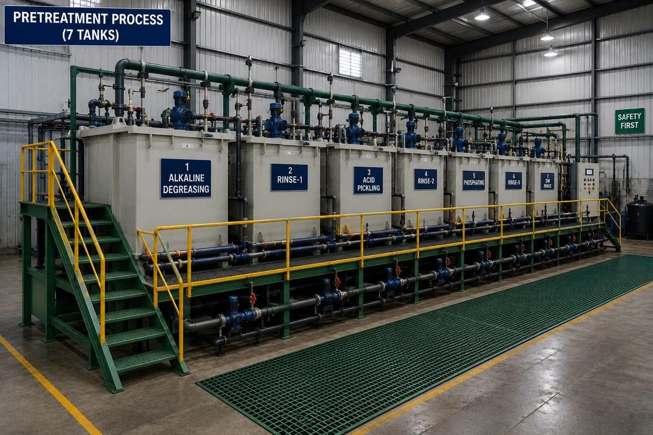
The seven-tank line runs degrease, rinse, descale, rinse, conversion coating, rinse and a demineralised final rinse. Skip the descale stage and the laser oxide lip on the cut edge survives under the conversion coat; the powder bridges it and the first stone chip lifts a 2 mm flake of coating with the oxide attached. That is a pretreatment decision, and it is visible in a cross-hatch test only after the part has seen moisture.
Weld seams under the hinge and around the latch plate must be coated, which means the seam has to be accessible to the spray gun and free of spatter. A 1 mm spatter ball at the hinge corner leaves a shadow that rusts first and looks like a paint defect. Grind spatter before pretreatment, not after coating.
The wider failure pattern on outdoor steel panels is set out in why powder coating fails on outdoor enclosures; the counterweight cover adds one twist — the rear face is hit by forks, so impact resistance matters as much as corrosion resistance. A 60 µm film chips more readily than an 80 µm one at the same impact energy, which is why the striker area is usually at the top of the range.
The counterweight cover route at Ganesh
The blank is nested on the 12 kW fibre laser with the 40 ft × 16 ft bed, which fits a full cover blank plus the hinge and latch plates on a single sheet, cutting the material handling to one lift. The crown and returns are formed on the 200 T, 5-axis brake with the 4,450 mm bed and Delem control — long enough that a 1.3 m cover is formed without repositioning, which removes the mismatch between left and right crown radii. Hinge plates and inner stiffeners are welded on the three CLOOS robotic MIG cells or at one of the 30+ manual stations, on fixtures built in our own tool room.
Coating runs through the seven-tank pretreatment and the 18 ft × 14 ft electrostatic powder booth, with the curing oven behind it. Thickness is checked with a DFT gauge and adhesion with a cross-hatch test on a coupon from each batch. We have run panel and enclosure work for Mahindra and Godrej & Boyce programmes; Ganesh holds the Mahindra Annual Commodity Award for sheet metal in the Farm Division.
Before quoting, we weigh the blank. A 1,240 × 900 mm blank in 2.0 mm CRCA comes to 1.116 m² × 15.7 kg/m² = 17.5 kg, and at 1.6 mm the same blank is 14.0 kg. That 3.5 kg difference changes the handling, the fixture and sometimes the packing, so it belongs in the quotation. The sheet metal weight calculator reproduces that figure for any blank you are designing.
Inspection points that catch a bad cover
Five checks catch almost every defect before dispatch, and all five are cheap once the fixture exists.
- Hinge pin location on the checking fixture, with a pin gauge through both leaves: ±0.5 mm from the datum.
- Latch striker face relative to the pin: ±1.0 mm, and the striker must sit square to the closing direction within 0.5°.
- Gap and flush against the cab datum with the cover closed: 3 ±1 mm, measured at four points along the seam.
- Flatness across the crown and the flat: 2 mm over 1 m with a straight edge, checked with the cover unlatched and resting on its hinges, because a clamped cover hides the drumming.
- Coating: DFT at five points including one edge and one weld seam, plus cross-hatch to ISO 2409 Gt0–Gt1 on a coupon per batch.
A first article inspection report with these five fields, plus the material mill certificate showing the IS 513 grade and heat number, is what a quality team needs to release the part. Ganesh provides PPAP and first article inspection where the programme requires it.
What to put on the drawing before you send it
- Mark the hinge axis and the latch striker as datum features with their tolerances, and leave the rest under a general tolerance block — ISO 2768-1 class m is realistic for a cover; class f is not.
- State the material as IS 513 grade D, thickness and the mill certificate requirement per heat.
- Give the crown radius as a range (R40–R80) rather than a single value, unless the seam line depends on it.
- Show the counterweight silhouette as a reference outline with the 6–8 mm clearance dimensioned from it.
- Call out the weld type at each joint — spot with pitch and nugget, or fillet with leg length — rather than a general "weld all round".
- Specify the coating system, the target DFT range and the adhesion test, and say whether a salt-spray duration is required.
- Give the checking fixture datum scheme, or ask for one to be proposed, so the inspection method is agreed before tooling.
- Add the annual quantity and the release pattern. Counterweight covers run in batches of 50–200 against a scheduled release, and that pattern decides whether a form tool is worth building.
When laser and brake is the wrong route
Below about 3,000 covers a year, laser cutting and brake forming is the right answer: no tooling cost, the crown radius can change between batches, and the ±0.5 mm tolerance is achievable. Above that, a single-stage form tool on a mechanical press takes the cycle from minutes to seconds, and the comparison of stamping and laser cutting by annual quantity shows where the crossover sits for parts of this size.
Three cases we would send elsewhere. A cover with compound curvature — a crown that also falls away towards the rear corners — needs a draw die and a blank-holder study, not a brake. A cover in aluminium for a battery truck needs different springback compensation and a different pretreatment; we cut and form aluminium, but the coating system has to be specified for it. And a cover supplied as a casting with a cosmetic skin bonded to it is not a sheet metal part at all.
Send the drawing with the two datums marked and the annual quantity stated, and the route, the tooling decision and the fixture cost can be settled before the quotation is issued. Ready-made checklists for the RFQ stage are at sheet metal RFQ checklist, and forklift parts similar to this one are listed under forklift sheet metal parts.
Frequently asked questions
What steel thickness is used for a forklift counterweight cover?
Most 2.5–3.5 t trucks use 1.6–2.0 mm CRCA to IS 513 grade D for the cover skin and 2.5–3.0 mm for the hinge and latch reinforcement plates. Below 1.6 mm the panel dents at the first fork impact; above 2.5 mm the crown radius becomes hard to hold without a draw die.
Why does my counterweight cover drum or oil-can when it is closed?
The flat between the crown and the latch is too large for the thickness, or the weld sequence pulled it. A 2.0 mm panel needs a bead or a return every 250–300 mm of unsupported width, and hinge plates should be welded after the crown is set, not before.
Can a counterweight cover be made without a press tool?
Yes, up to roughly 3,000 covers a year. Laser cutting plus a 200 T press brake with a radius punch holds the crown and the wrap bends to ±0.5 mm. Above that volume a single-stage form tool pays back because the brake cycle and the template check disappear from the cost.
How thick should the powder coating be on a forklift body panel?
60–80 µm of polyester powder over a zinc phosphate conversion coat is the working range for outdoor yard exposure. Under 50 µm the edges and weld seams rust first; above 100 µm the film chips at the latch striker where it takes impact.
How is the cover checked before dispatch?
On a checking fixture that carries the hinge pin and the latch striker: pin location to ±0.5 mm, latch face to ±1.0 mm, gap and flush against the cab datum to 3 ±1 mm, flatness to 2 mm over 1 m, plus coating thickness and a cross-hatch adhesion test.
Sources and further reading
- IS 513 — Cold reduced low carbon steel sheets and strips (grades D and DD) · reviewed 3 Nov 2026
- ISO 2768-1 — General tolerances for linear and angular dimensions without individual tolerance indications · reviewed 3 Nov 2026
- ISO 2409 — Paints and varnishes: cross-cut test · reviewed 3 Nov 2026
- ASTM B117 — Standard practice for operating salt spray (fog) apparatus · reviewed 3 Nov 2026
Have a counterweight cover drawing ready?
Send the current revision with the hinge and latch datums marked, the material grade and the annual quantity. Our engineering team reviews the route, the tooling decision and the fixture before quotation.
Request a quote