Key takeaways
- Size the frame from the balance mass, not the car: a 600 kg car with a 408 kg rated load at 50% balance needs 804 kg of counterweight, which is 59 filler plates of 13 kg at 300 × 200 × 30 mm.
- Hold the guide shoe bracket holes to ±0.5 mm and the frame diagonals to 1.5 mm; a 2 mm twist across the frame wears the guide shoes on one rail within a few thousand trips.
- Take the coating off the guide shoe mounting face or add its thickness to the bracket datum; 85 µm of hot-dip zinc per face becomes 0.17 mm on a face that sets the shoe gap.
- Clamp the filler stack with tie rods preloaded to at least 60% of proof load and re-torque after the first 500 trips, or the stack rattles and the rods fatigue at the thread root.
- A 3.0 mm formed channel is the right side member for frames up to about 1,200 kg; above that, go to 4.0 mm plate or a welded box, because the deflection under a safety-gear trip is what cracks the shoe bracket, not the static load.
Two frames that look identical on a drawing sheet behave differently in a shaft. One runs quietly for a decade; the other wears a guide shoe every 20,000 trips and rattles at every start. The difference is usually in three numbers: the balance mass the frame was sized for, the diagonal tolerance it was built to, and the coating thickness left on the shoe mounting face.
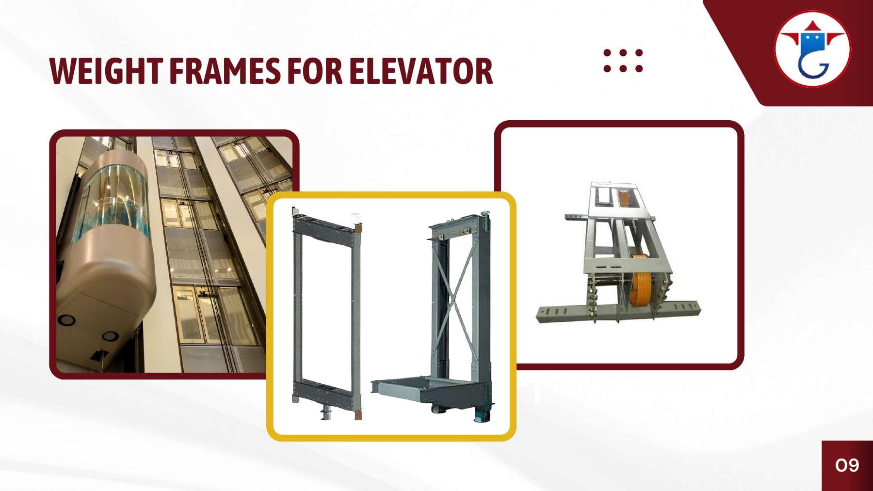
An elevator counterweight frame is a welded steel structure that carries a stack of cast iron or steel plates and runs in the same guide rails as the car. It hangs from the ropes on a hitch plate, carries four guide shoes at its corners, and provides the mass that offsets the car. This guide covers how that mass is calculated, how the frame section follows from it, where the tolerances have to sit, and what the cut-form-weld-coat route has to do to meet them.
The frame discussed here is a two-rail passenger lift frame of 1,800–2,600 mm height, built from 3.0 mm formed channel side members and 4.0 mm cross members, carrying 250–1,200 kg of filler. The same principles apply to the smaller frames used on goods lifts and to the split frames used where the shaft height limits a single stack. Ganesh supplies elevator frames and lift components to TKE and Eros Elevators; the elevator components hub collects the related guides on rails, doors, sills and car frames.
How much counterweight does the frame have to carry?
Counterweight mass is the car deadweight plus 40–50% of the rated load. The 50% figure is the usual balance point for a passenger lift because it equalises motor torque between an empty car going up and a full car going down; 40% is used where the lift runs mostly lightly loaded.
Work it through for a six-person lift. The car, sling, doors and fittings weigh 600 kg. The rated load is 408 kg. At 50% balance the counterweight is 600 + 0.5 × 408 = 804 kg. The frame itself weighs 40–50 kg, so the filler stack is about 760 kg. A 300 × 200 × 30 mm cast iron plate at 7,200 kg/m³ weighs 12.96 kg, which gives 59 plates and a stack height of about 1,770 mm before spacers.
That stack height is what sets the frame height, and the frame height is what sets the shaft pit depth and the overhead. Change the plate size and you change the frame, the guides and the buffer position. Note the order of the calculation: the mass comes first, the frame follows it, and the shaft follows the frame. Frames are frequently re-detailed because the machine-room layout was fixed before the balance calculation was done.
Choosing the frame section
Three sections are used for frame side members, and the choice follows the stack height and the mass.
Formed channel, 3.0 mm. The default for frames up to about 1,200 kg and 2,600 mm. A 100 × 50 × 20 mm channel formed from 3.0 mm IS 513 sheet weighs about 4.6 kg/m and has enough section modulus to carry the stack without visible bow. It is formed on a press brake, which means no tooling cost and a cheap route for low volumes.
Welded box, 3.0–4.0 mm. Two channels back to back, or a plate box welded from four strips. Stiffer in torsion, which matters where the frame is longer than the guide shoe spacing and the shoes have to keep the frame from rocking. The cost is welding time and distortion control.
Plate, 4.0–6.0 mm. Used on heavy goods lifts and where the frame also carries a safety gear and a rope hitch machined after welding. Plate frames are laser cut with the shoe bracket holes in place, which removes the drilling operation and the position error that comes with it.
The section is chosen on stiffness under the safety-gear load, not on static strength. A formed channel that carries 1,200 kg happily in normal running can deflect 3–4 mm at the top member under a trip, and that deflection is what loads the shoe bracket weld.
| Parameter | Typical value for a 408–630 kg passenger lift | Ganesh limit or note |
|---|---|---|
| Side member | 3.0 mm IS 513 formed channel, 100 × 50 × 20 mm | Formed on the 200 T, 5-axis brake with a 4,450 mm bed |
| Top and bottom cross member | 4.0 mm IS 2062 E250 plate | Laser cut to 20 mm; hole pattern cut in the same pass as the outline |
| Frame overall height | 1,800–2,600 mm | 4,450 mm bed takes a full side member in one forming pass |
| Frame width | Filler width + 3 mm total clearance | Clearance 1.5 mm per side; tighter and the stack will not drop in |
| Frame height tolerance | ±2.0 mm | Checked on a fixture, not on a surface plate |
| Width tolerance | ±1.5 mm | ±0.5 mm typical on sheet metal features; the frame is a weldment |
| Diagonal difference | 1.5 mm maximum | Measured across the shoe bracket holes, not the outside corners |
| Shoe bracket hole position | ±0.5 mm from frame datum | Jig-drilled or laser cut with the bracket; the shoe has only 2–3 mm of adjustment |
| Tie rod | 2 × M16 grade 8.8, preload ≥ 60% of proof load | Rod holes drilled after welding to keep them coaxial |
| Weld leg, frame joints | 4 mm fillet, semi-automatic MIG | Robotic MIG cells for repeat frames; fixtures built in-house |
| Coating | Hot-dip zinc 85 µm per face, or powder 60–80 µm | Coating adds 0.17 mm per face; mask the shoe mounting face |
| Rope hitch plate | 8–10 mm plate, holes machined after welding | Machined after welding so the rope centres match the sheave |
Where the tolerances have to sit
A counterweight frame has one job beyond carrying mass: it must run in the rails without loading the shoes. That makes the four shoe bracket positions the only critical dimensions on the part, and everything else secondary.
The shoe brackets are welded to the frame at the corners and carry a sliding shoe that runs on the rail head. The shoe has 2–3 mm of lateral adjustment by shims, so the bracket hole position has to be within ±0.5 mm to leave that adjustment usable. The bracket face also has to be square to the rail direction within about 0.5°, or the shoe wears on one edge of its liner.
Diagonals matter more than any single dimension. If the two diagonals across the shoe bracket holes differ by 2 mm, the frame sits in the shaft as a parallelogram, and the shoes push the frame against one rail. The wear shows up first as a polished stripe on one shoe liner and a rattle at the top landing, and it is not repairable by adjusting the guides.
Frame height carries ±2 mm because it stacks into the pit buffer position and the overhead clearance. Width carries ±1.5 mm because it sets the filler clearance.
The stack itself is a separate fit: 1.5 mm clearance per side lets the plates drop in, and 3 mm total clearance stops the stack from transferring load to the side members as the frame sways.
Welding a frame that has to stay straight
The frame is a four-corner weldment with two long side members and two short cross members, and the weld pulls the corners. A 4 mm fillet on each side of a 100 mm connection shrinks about 1–1.5 mm per metre of weld; on a 2,000 mm frame with eight such connections, the diagonals can move 3 mm if the sequence is left to the operator.
The sequence that holds: tack the frame square in the fixture, weld the top member to both sides in one pass, let it cool, then the bottom member, then the shoe brackets. Welding the four corners in a single heat run puts all the shrinkage into the last corner.
The weld sequence and the fixture discipline for a formed-and-welded frame are the same as for any stiffened steel structure; the general guide to welded assembly tolerances explains where the last millimetre is lost when a frame is joined to its brackets. A frame welded from plate rather than formed from channel has a different distortion problem, covered in welded elevator counterweight frames, and the overview of why the counterweight frame is harder than it looks sets the wider context.
After welding, the frame is checked for twist by placing it on three points and measuring the fourth corner. A 1.5 mm lift indicates twist that will show up as uneven shoe wear. Heat straightening a twisted frame is possible on 3.0 mm channel with a neutral flame and a water quench, but it softens the weld toe, so it is a correction of last resort on frames that must pass a fatigue review.
Corrosion protection and the coating allowance
A counterweight frame lives in the shaft, which is humid, poorly ventilated and occasionally flooded. It is inspected rarely and repaired never. Protection therefore has to be robust to a single application, which pushes the choice towards hot-dip galvanising.
Galvanising adds a zinc layer of about 85 µm per face on 3–6 mm steel, so 0.17 mm on a dimension. That matters in three places. The guide shoe mounting face grows by 0.17 mm, which closes the shoe gap; mask it or machine it after galvanising. The filler clearance shrinks by 0.34 mm across the frame width, which is why the 3 mm total clearance in the table is not generous. And the rope hitch hole grows by nothing — but zinc can bridge a 10 mm hole if the part is dipped without a vent, which is why every closed section needs a 10 mm drain hole at the lowest point and a vent at the highest.
Powder coating at 60–80 µm is used where the shaft is dry and the frame is in a machine-room-less package behind a cladding panel. The weakness is the weld seam and the inside of the channel, which the spray gun cannot see. The line runs seven-tank pretreatment, and the DFT is checked on the visible faces; treat the inside of a formed channel as unpainted in any corrosion estimate.
For frames that combine a galvanised structure with a painted hitch plate, mask the machined faces before either process. A painted rope hitch plate is a wear surface that will frett the rope socket.
What Ganesh runs for counterweight frames
Side members are cut on the 12 kW fibre laser and formed on the 200 T, 5-axis brake with the 4,450 mm bed, which takes a 2,400 mm member in a single hit and keeps the channel legs square to each other. Cross members and shoe brackets are laser cut with their holes in place where the design allows, and frames are welded on fixtures built in our own tool room, on the three CLOOS robotic MIG cells or at the manual stations. Painted frames run through the seven-tank pretreatment and the 18 ft × 14 ft powder booth; the DFT gauge and cross-hatch test are used on the coated frames.
Frames and car components for TKE and Eros Elevators have gone through this route, and the dimensions that matter — shoe bracket positions, diagonals and hitch hole centres — are checked on a fixture before dispatch, with a first article inspection report on new drawings. Elevator frames, sills, brackets and door parts are listed under elevator sheet metal parts.
What the lift drawing has to settle
- The balance mass, the filler plate size and the plate count, so the frame height is derived rather than assumed.
- The rail size and the shoe type, because the shoe bracket face geometry follows the rail head.
- Shoe bracket hole positions dimensioned from a frame datum, with ±0.5 mm and the diagonal limit stated.
- The section of each member, with the material standard and thickness, and the weld leg for each joint.
- The coating system, its thickness and the faces that must be masked.
- The rope hitch plate as a machined item with the hole centres toleranced after welding.
- The drain and vent holes for galvanising, with their positions and minimum diameter.
- The safe working load and the safety-gear type, so the frame can be checked under the trip load.
Ready-made fields for this list are in the RFQ checklist, and a frame that has been through this review quotes faster because the questions have already been answered.
When a fabricated frame is the wrong answer
Three cases. A frame that must carry more than about 2,000 kg of filler on a 2,600 mm height is usually a plate structure with a machined hitch, and the fabrication moves from sheet metal into heavy plate work. A frame for a hydraulic lift with a different suspension geometry is a different design and should not be adapted from a traction frame. And a frame that will be installed in a shaft with no corrosion protection at all — an outdoor observation lift, for example — needs a duplex system (galvanised and painted), which adds a second coating stage and a longer lead time on the coating line.
For frames inside those limits, the cut-form-weld-coat route holds the ±0.5 mm bracket position and the 1.5 mm diagonals that keep a lift quiet. The detail that most often gets lost between design and fabrication is the coating allowance on the shoe face: 0.17 mm per face is invisible on a drawing and decisive in a shaft.
Frequently asked questions
What thickness steel is used for an elevator counterweight frame?
Most machine-room and machine-room-less passenger lifts use 3.0 mm formed channel to IS 513 for the side members and 4.0 mm plate for the top and bottom cross members. Above roughly 1,200 kg of counterweight, or where the frame is longer than 2,600 mm, 4.0 mm plate or a welded box section is more reliable than a formed channel.
How is the counterweight mass calculated?
Counterweight mass equals car deadweight plus 40–50% of rated load. A 600 kg car with a 408 kg rated load at 50% balance needs 804 kg total. Subtract the frame mass, typically 40–50 kg, and divide by the filler plate mass to get the plate count.
Should a counterweight frame be galvanised or powder coated?
Hot-dip galvanising is the better choice in a damp shaft or where the pit floods, because the frame is rarely inspected and a powder film fails silently at the weld seams. Whichever is used, mask or machine the guide shoe mounting face, because coating thickness on that face changes the shoe clearance.
Why does a counterweight frame rattle?
The filler stack is loose. Tie rods that are torqued to a low value, or rods sized for the static weight rather than for the clamp load, allow the plates to move against each other as the car starts and stops. Rattle is also a precursor to rod fatigue, so it should be fixed rather than tolerated.
What tolerance can a fabricator hold on a counterweight frame?
Frame height ±2 mm, width ±1.5 mm, diagonals within 1.5 mm, and guide shoe bracket holes at ±0.5 mm from the frame datum. Ganesh holds ±0.5 mm on named sheet metal features and tighter by agreement; a fabricated frame of 2,000 mm or more is checked on a fixture rather than on a surface plate.
Sources and further reading
- IS 14665 — Electric traction lifts, Parts 1 to 4 (outline dimensions, safety rules and testing) · reviewed 3 Nov 2026
- IS 2062 — Hot rolled medium and high tensile structural steel · reviewed 3 Nov 2026
- ISO 2768-1 — General tolerances for linear and angular dimensions without individual tolerance indications · reviewed 3 Nov 2026
Have a counterweight frame drawing?
Send the frame drawing with the filler stack, the rope hitch detail and the guide shoe bracket positions. We will confirm the section, the weld sequence and the fixture before quotation.
Request a quote