Key takeaways
- A 80 µm coat on the bore of a hole reduces its diameter by 0.16 mm, which is harmless on a 9.0 mm clearance hole for an M8 bolt and fatal on an 8.0 mm dowel hole.
- Coating reduces the pitch diameter of a 60° thread by 2.31 times the coating thickness, so 80 µm takes 0.185 mm off an M8 thread, more than the whole 6H tolerance band.
- Powder build inside a hole falls to 30–60% of the face value once the depth exceeds the diameter, so the allowance is not simply two times the face thickness.
- Every feature that must stay bare — threads, earth studs, dowel bores, countersink seats — needs a masking callout on the drawing, because the masking is a process step with its own cost.
An M8 nut runs down a coated stud for three turns and stops. The thread was cut to 6g, the coat is 80 µm, and the assembly cannot close. Coating build in holes and threads is a dimensional change, and the drawing that ignored it specified a part that cannot be built.
The effect is small enough to be forgotten and large enough to stop a line. An 80 µm powder coat takes 0.16 mm off a bore diameter and 0.185 mm off the pitch diameter of an M8 thread, which is more than the entire 6H tolerance band. This article gives the arithmetic for both, the masking decisions that avoid it, and the drawing callouts that make the choice explicit.
The design and CAD hub collects the rest of this cluster, from bend allowances to datum schemes.
What coating does to a bore
A bore shrinks by twice the coating thickness measured on its wall. For an 80 µm build that is 0.16 mm, so a 9.0 mm hole finishes at 8.84 mm.
Two corrections stop that number from being pessimistic. The first is that powder does not reach the inside of a hole in the same quantity as the outside. Electrostatic powder is drawn to the nearest earthed surface, and a hole deeper than its diameter screens the field, so a bore with a depth-to-diameter ratio above 1 typically picks up 30–60% of the face build. At a face build of 80 µm the bore build is nearer 30 µm a side, so the diameter loss is about 0.06 mm rather than 0.16 mm.
The second correction is the geometry of the edge. The coating wraps the hole's radius or chamfer and thickens at the lip, so the entry of a hole is tighter than the bore by a few hundredths of a millimetre. On a hole that a bolt passes through this does nothing. On a hole that a dowel enters with an H7 fit it is the difference between an assembly and a hammer.
The practical rule is to work with the face figure and treat the bore reduction as a maximum. If the maximum still leaves you outside the fit, the feature needs masking, and no amount of bore-thinning argument will rescue it.
The same thinning shows up at the cut edge of a laser-cut hole. Coating pulls back at a sharp edge because the surface tension of the molten powder film cannot hold a right angle, so edge coverage is commonly 30–50% of the face build. The hole lip therefore has less protection than the face around it, and on a part that will be washed or rained on, the bore entry is where corrosion starts. ISO 2409, applied to a cross-cut that crosses the bore edge, is the check that the film there is stuck rather than merely present.
Powder against wet paint
The two finishes build differently inside a hole, and the difference is not the total thickness.
A powder coat is applied as a dry, charged particulate and cured into a film, so the build inside a bore is set by how much powder the electrostatic field delivered. A wet paint arrives as a solvent-borne film that flows, and it wets the bore wall far more readily, so a two-coat wet system at 30 µm a coat puts a more even 60 µm into a hole than an 80 µm powder coat does.
The rule of thumb that survives both: work out the allowance from the face build, then check the bore with a pin gauge or an internal micrometer on the first article rather than trusting the calculation. A 0.02 mm error in the assumed bore build is 0.04 mm on the diameter, which is the whole clearance on a dowel fit.
A worked example: the hinge bracket
A bracket has a Ø10 H8 bore for a Ø9.95 hardened pin, giving a diametral clearance of 0.05–0.07 mm. That is a bearing fit with a little room for grease.
Coat the part at 80 µm on the face and the bore picks up about 30 µm a side. The bore closes to 9.94 mm at its maximum material condition. The pin no longer enters, and the part fails at assembly with a defect that is nowhere on the drawing.
Three fixes, in order of preference. Mask the bore, coat, then ream it to H8, which puts a bare edge inside a protected bore and is the right answer for a moving joint. Leave the bore oversize by 0.06 mm before coating so it lands at nominal, which only works if the bore build is repeatable to about 0.01 mm, and it is not. Or move the bearing to a bushing pressed in after coating, which costs a pressed part but removes the argument permanently.
Threads, and why the allowance is 2.31 t
A thread is two flanks at 30° to the screw axis. Coating of thickness t deposited normal to each flank reduces the pitch diameter by 2t / cos 30°, which is 2.31 t. At 80 µm that is 0.185 mm.
The 6H tolerance band on an M8 × 1.25 pitch diameter is 0.160 mm. The build is larger than the whole band, before any allowance for the thread's own manufacturing tolerance. That is why a coated thread does not assemble: it is not a marginal interference that a wrench overcomes, it is a thread that has been made smaller than any 6g bolt can enter.
The same arithmetic on an M6 × 1.0, where the 6H band is about 0.150 mm, gives 0.185 mm of build against a still smaller band. Small threads are worse, not better, because the tolerance band shrinks with the diameter while the coating thickness does not.
Coating build in holes and threads: the sizes that work
The table below works through the features that come up on an enclosure panel, with the pre-coat size that holds the fit at a face build of 80 µm.
| Feature on a 3 mm CRCA panel | Nominal (mm) | Coat at 80 µm | Pre-coat size to hold the fit | Ganesh limit or note |
|---|---|---|---|---|
| Clearance hole, M8 bolt (ISO 273 medium) | 9.0 | 8.84 | 9.0 as drawn | Accepts build without masking; mask only on a visible face |
| Close clearance hole, M8 | 8.4 | 8.24 | 8.4 as drawn | Tightest hole an M8 shank will pass after coating |
| Tapped M8 × 1.25, 6H | 7.188 pitch dia | 7.003 pitch dia | Mask the thread | Coated thread fails 6g entry; 2.31 t reduction |
| Dowel bore, Ø8 H8 | 8.000–8.022 | 7.94 | Mask, or bore after coating | Machining after coating leaves a bare edge; specify it |
| Countersink seat, 90° | flush | 0.11 mm proud | Mask the seat | Flushness callout tighter than 0.2 mm needs masking |
| Earth stud or pad | bare metal | 2.4 kV stand-off | Mask a 20 mm pad | Toothed washer is the fallback, not the plan |
| Thread-forming screw hole, M5 | 4.6 | 4.44 | Mask, or open up by 0.16 | Opening up loses thread engagement; test before release |
| Hinge pin bore, Ø10 | 10.0 H8 | 9.94 | Mask and ream after coating | Coating inside a moving bearing is a wear surface |
The second column is the number most drawings carry, and the fourth is the number the part actually needs. Where the two differ, the drawing has to say which side of the coating the dimension applies to, and that is a note, not a work instruction.
Masking: the honest cost of a bare feature
Masking is a manual operation before the part enters the booth and another one after it leaves the oven, and both ends cost money and carry a failure mode.
Powder coating cures at 180–200 °C for 10–20 minutes, so the mask has to survive the cure. Silicone plugs and caps do. Polyethylene caps deform and leave a ring of coating that has to be cut away. Tape works on flat pads and fails in a hole, because the plug has to be seated below the surface or the coating bridges over it.
Three masking strategies fit different features:
- Plugs and caps for threads and bores, sized to the pre-coat dimension. A plug that is a loose fit lets powder creep past and a plug that is too tight will not come out of a cured part.
- Masking tape or a magnetic disc for flat earth pads and mating faces, where the pad is larger than any plug.
- A post-coat operation for features that must be precise: ream, chase or face after the oven. This is accurate and it leaves a bare edge that corrodes first, which is why it is the last choice on a part that will see weather.
A masking specification that lists one generic note, "mask threads", is the one that fails. The list has to name the features by hole size and position, because a plug kit is ordered against that list and the operator at the booth works from it.
What the coating process does that a drawing can count on
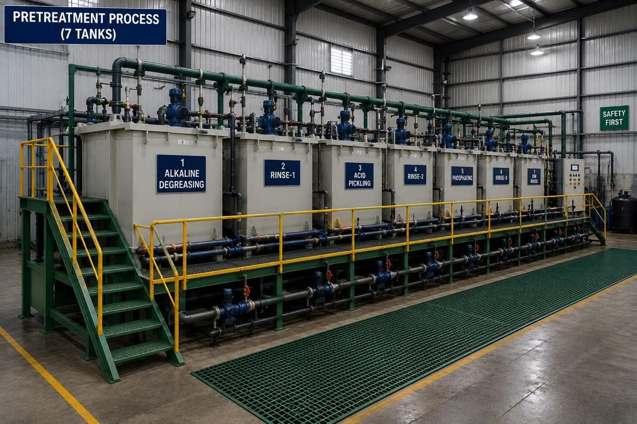
The build is set by the process, so the drawing should specify the finish and let the supplier hold the thickness to it. At Ganesh, coated parts pass through seven-tank pretreatment and a 16 ft × 16 ft shot blast chamber before the 18 ft × 14 ft electrostatic powder booth, the wet paint booth and the curing oven. The paint shop capability sets out the line, and the seven-tank pretreatment article explains what each stage does to adhesion.
Dry film thickness is measured with a gauge to ISO 2808, and adhesion is checked with a cross-hatch to ISO 2409, which is the test that finds a coat that looked correct and lifts from the substrate. Both matter to a bore, because a plug that let powder creep in produces a thin, poorly adhered film in the one place nobody inspects.
The build a buyer should specify depends on the environment. ISO 12944-2 classifies the corrosivity of the surroundings, from C1 indoors to C5 at sea or in a chemical plant, and the coating system has to match the category rather than a house preference. A 60–80 µm powder coat suits a moderate environment with good pretreatment; a C4 or C5 exposure needs a higher build or a duplex system, and the outdoor enclosure failures article covers what happens when a thin coat meets a wet coastal atmosphere.
Thicker is not automatically better. Past about 120 µm a powder coat becomes brittle and chips at cut edges, and it makes every masked feature tighter. Specify the range, not a minimum.
What to put on the drawing
Six notes cover most of it, and they belong in the title block or against the view rather than in a general note about finishes.
- Finish and colour, with the coat type, for example polyester powder, RAL number, 60–100 µm.
- The dimension basis: dimensions apply before coating, or after coating. State it once and mean it.
- Masked features, listed by feature, size and location: threads, bores, earth pads, mating faces.
- Coating-free zones, drawn as a hatched area with a dimension, for a face that must bolt to another part.
- Thread callouts with the class, 6H for internal, and a note that the thread is masked or coated, so the supplier does not guess.
- The inspection point, which is the dry film thickness on a named face, and the adhesion test class.
A drawing that gives the thread class but not the masking decision has given the supplier a specification that cannot be met. The supplier then either coats the thread and returns an unbuildable part or masks it without being told and adds a cost that was not quoted.
When the feature should not be in a coated part at all
The most reliable fix is a design change that removes the coating from the fit.
Move the thread into a weld nut, a rivet nut or a captive fastener fitted after coating, so the thread is never near the booth. Use a stud welded before coating and masked at the base, rather than a tapped hole in a 1.5 mm panel. Put the precision bore in a separate machined insert, or in a bracket that is assembled after painting.
Some parts should not be powder coated at all. A part with a sliding bore, a close-tolerance datum face and a decorative face wants a different finish on each area, and the cheapest answer is often to coat the outside and leave the inside bare, which is a masking decision as much as a design one. Where the whole part must be conductive, an e-coat or a zinc plating on a masked area is more coherent than a powder coat with twenty holes plugged out of it.
The cost conversation belongs at quotation, not at first article. A drawing with 14 masked threads prices differently from one with none, and the difference is visible in the quotation only if the drawing says what has to stay bare.
Send the drawing with the finish specification, the dry film thickness, the fasteners and the features that must stay bare, and the engineering team will check the allowance against ISO 273 clearance sizes for the bolts actually specified before the part is released to the line.
Frequently asked questions
How much does powder coating reduce a hole diameter?
Twice the coating thickness on the bore, so 0.16 mm for an 80 µm coat on a through hole. The real figure is usually lower because powder builds less inside a hole than on the face, and about 0.06–0.10 mm per side is normal at a face build of 80 µm.
Can you powder coat over threads?
You can, but the thread will not assemble. The coating reduces the pitch diameter by 2.31 times its thickness, and 80 µm takes it past the 6H tolerance. The options are masking, a coating-free zone, or moving the thread into a weld nut or a captive fastener.
Do I need to specify masking on the drawing?
Yes, if the feature must stay bare. Masking is a manual step with its own cost and its own failure mode, and a supplier who is not told will coat the part evenly and hand back a thread that has to be chased with a tap.
How thick should a powder coat be for outdoor use?
In the range of 60–100 µm on a properly pretreated face for a moderate-corrosion environment, with a higher build or a duplex system for the severe categories in ISO 12944-2. Thicker is not automatically better: beyond about 120 µm the coat becomes brittle at edges and chips.
Does coating affect earth continuity?
Yes. A cured polyester powder coat is a dielectric with a breakdown strength of roughly 30 kV/mm, so 80 µm stands off about 2.4 kV. An earth point needs a masked pad, a stud left bare, or a toothed washer that bites through the film.
Sources and further reading
- ISO 12944-2 — Paints and varnishes: corrosion protection of steel structures by protective paint systems, classification of environments and the build each category needs · reviewed 3 Nov 2026
- ISO 2808 — Paints and varnishes: determination of film thickness, the method behind the dry film thickness reading taken on the part · reviewed 3 Nov 2026
- ISO 2409 — Paints and varnishes: cross-cut test, used to check that the coating over a masked edge or a bore still adheres · reviewed 3 Nov 2026
Send the drawing with the threads and bores marked
Include the finish specification, the dry film thickness, the features that must stay bare and the mating fasteners. We will check the allowance before the part reaches the line.
Request a quote