Key takeaways
- MIG welding leaves glassy silica islands 1–3 µm thick along the bead; they are insoluble in alkaline cleaning and only blasting, grinding or an HF-containing acid removes them.
- A re-entrant weld toe presents less than 90° to the gun, so film at the toe runs 50–70% of the flat-face build and the cross-cut fails there first.
- Blast the weld zone to Sa 2½ with a 40–70 µm anchor profile before pretreatment; degreasing removes oil and fume but leaves scale, islands and spatter untouched.
- On galvanised work, grind the zinc back 50 mm each side of the weld, then restore the stripped ring with a zinc-rich coat, because that ring is the first place to rust.
- Grade the result to ISO 2409 with a 2 mm cut spacing at a 61–120 µm film, and record where the lattice crosses the weld, not just the grade on the flat.
A welded canopy frame comes off the line at 75 µm on the face, passes a cross-cut at G0 on the flat panel, and lifts at G3 within 20 mm of the weld toe. Same powder, same batch, same cure, same operator. The difference is the 6 mm of surface the welder touched.
Paint adhesion after welding is decided by what the arc left behind and by the angle of the surface the film has to cover. Both are fixable, and neither is fixed by cleaning harder with the same chemistry, because the residue is not grease.
The rule is short: remove the weld residue mechanically, reach the toe with the blast, and measure the result where the lattice crosses the seam rather than on the flat. The rest of this article is what each residue does and the numbers that make the preparation inspectable.
Paint adhesion after welding: what does the weld leave behind?
Six things, and they fail the coating for different reasons: silica islands, spatter, mill scale not removed by the arc, heat tint on stainless, fume condensate and geometric defects at the toe.
Silica islands are the one that surprises people. MIG deoxidiser is a manganese-silicon alloy, and it floats out of the pool as a glassy film along the bead edge, typically 1–3 µm thick and sometimes in patches a millimetre across. Glass does not dissolve in an alkaline cleaner at pH 9–11, and it does not burn off in the cure oven at 180–200 °C.
Spatter is metallic and sits proud of the surface by 0.2–1 mm. Mill scale survives inside the weld zone on hot-rolled stock because the arc does not reach the 10–20 mm either side. Heat tint on stainless is a chromium-depleted oxide that corrodes under the film even when the film adheres.
Why alkaline cleaning cannot fix it
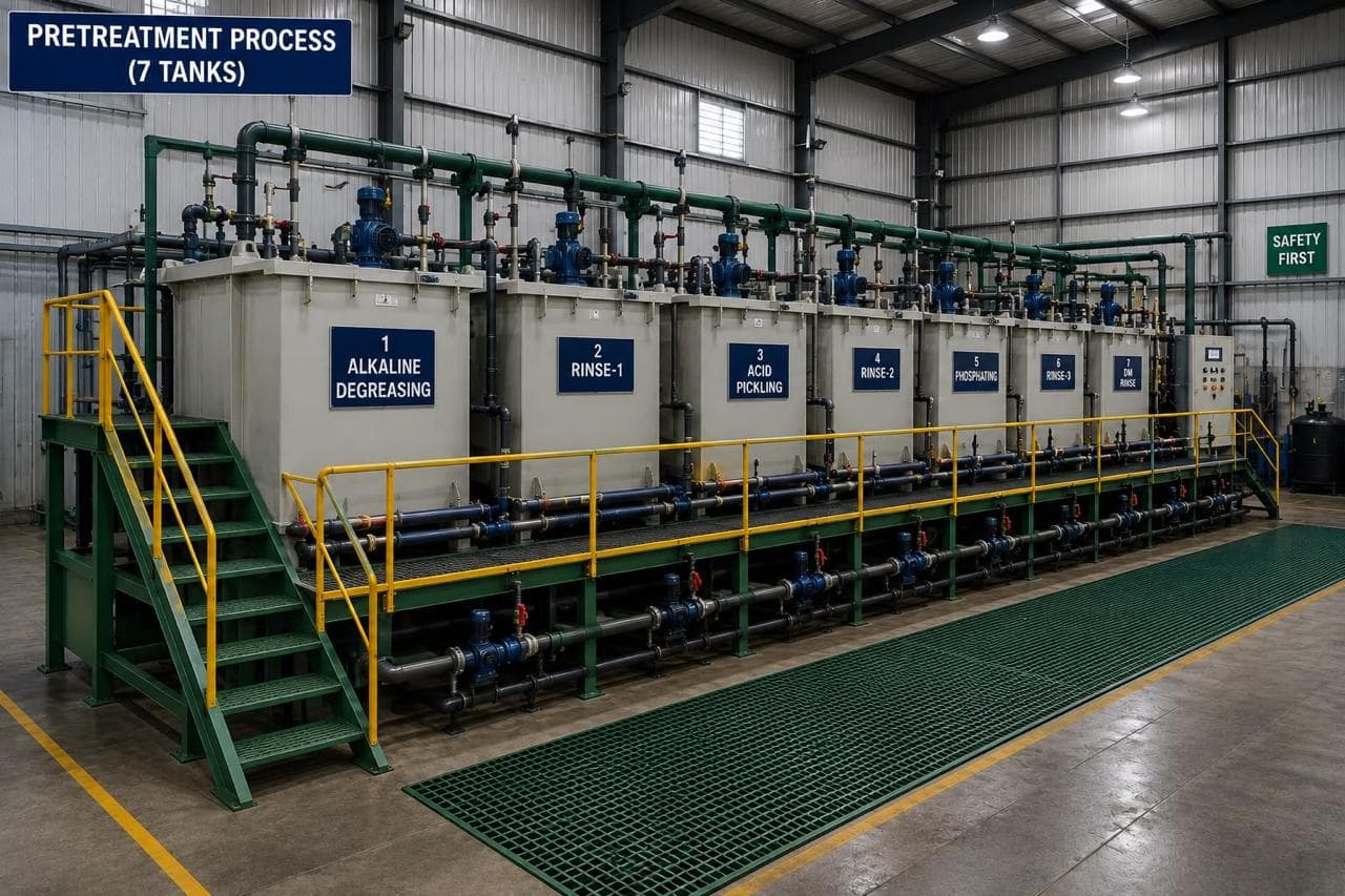
The seven-tank line starts with an alkaline degrease because the job of that tank is oil, drawing lubricant and handling soil. It is good at that. It is not designed to dissolve an oxide or a silicate, and no increase in concentration or temperature will make it.
The result is a part that passes a water-break test, passes a tape test on the flat, and fails at the seam. The contamination is under the film, not on it, and the only tests that find it are the ones that pull the film off.
Wire brushing is not preparation
A wire brush on a grinder removes loose spatter and puts a shine on the bead. It does not remove silica islands, because they are harder than the wire and sit in the valleys the brush cannot reach, and it does not remove mill scale from the parent plate.
It also contaminates. A brush that has been used on galvanised work carries zinc into the weld zone, and a brush used on stainless carries iron into it, which rusts on the surface within weeks. Keep separate brushes for carbon steel, stainless and galvanised, and treat brushing as a cleaning step, not a preparation step.
The test is simple: brush a bead, then blast the same area to Sa 2½ and look at the difference under a low-angle light. The blasted area is uniformly grey with a visible profile; the brushed area still shows the island line and the original scale boundary.
Coverage is the other half. A 40 µm profile measured on the flat says nothing about the 6 mm of toe beside it, so use a replica tape or a comparator on the toe itself, and look for a uniform grey with no shadow line along the bead. A shadow line means the nozzle never crossed the toe at an angle, and the island line underneath is still there.
Stainless is a separate route
A stainless weld leaves heat tint, and the tint sits over a chromium-depleted zone. Blasting removes the colour and some of the oxide, but it does not restore the chromium, so the tinted band corrodes under a film that adheres perfectly. Pickling or a pickling paste is the only preparation that removes the depleted layer.
We do not pickle in-house. A stainless assembly that needs pickled welds is quoted with that step identified and scheduled, because the pickling has to happen before pretreatment and after the weld, and the rinse water from the paste is a waste stream of its own.
What each weld condition does to the bond
| Weld condition | Residue left | Effect on the coating | Preparation that works | Ganesh limit or note |
|---|---|---|---|---|
| MIG bead edge | Silica islands, 1–3 µm | Interfacial failure at the island, G2–G4 | Blast to Sa 2½ or grind the bead edge | Robotic cells leave a more consistent island line |
| Spatter within 30 mm | Metallic balls, 0.2–1 mm | Film thins to 30% at the shoulder | Chip, then blast | Inspected before the booth |
| Mill scale beside the weld | Oxide, 5–20 µm | Adhesion loss plus under-film corrosion | Blast to Sa 2½ | Hot-rolled stock only; CRCA has none |
| Heat tint on stainless | Chromium-depleted oxide | Adhesion plus tea staining at the tint | Pickle or a pickling paste | Not done in-house; flag at enquiry |
| Fume condensate | Oily film | Crawling, craters, pinholes | Alkaline degrease, then rinse | Removed in tank one |
| Undercut or porosity | Void under the film | Outgassing blisters at cure | Cut out and re-weld | ISO 5817 level sets the acceptance |
| Convex, smooth toe | No re-entrant angle | Film 85–100% of face | Nothing; this is the target | Preferred toe for coated parts |
| Sharp, deep toe | Re-entrant angle under 90° | Film 50–70% of face | Radius the toe or dress it | Toe dressed on visible seams |
| Galvanised weld zone | Zinc burned back 10–20 mm | Bare ring, white rust then red | Grind 50 mm each side, zinc-rich coat | Duplex route needs a galvaniser |
The Ganesh column is where the line sets the standard. We can blast, degrease, phosphate and coat in-house, and we can dress a toe to a radius on a visible seam. We do not pickle stainless in-house, so a heat-tint requirement on a stainless weld is quoted with that step identified rather than assumed.
Why the toe fails before the bead
Two mechanisms meet at the toe. The first is geometry: a fillet weld meets the parent plate at an angle that is often less than 90°, and a powder gun is a line-of-sight device. Particles of 20–40 µm follow the field to the nearest grounded surface, and a re-entrant corner presents very little of itself.
The measured result is consistent with the edge data: 50–70% of face film at a sharp toe, 85–100% on a convex, dressed toe. On an 80 µm face build that is 40–56 µm at the toe, which is below the 60 µm that a C3 specification assumes and well below what a C4 system needs.
The second mechanism is contamination. The silica island line runs along the same toe, so the thinnest film sits on the least bondable surface. Either alone is survivable. Together they are why the cross-cut lifts at the seam and nowhere else.
Cross-cut spacing changes the answer
ISO 2409 grades adhesion by cutting a lattice through the film and counting what lifts. The cut spacing is set by film thickness: 1 mm spacing for films up to 60 µm, 2 mm for 61–120 µm, 3 mm for 121–250 µm. At a 75 µm build the spacing is 2 mm, six cuts each way.
That matters at a weld because the lattice has to cross the toe to test it. Six cuts at 2 mm spacing covers 10 mm, which is enough to span the bead and both toes on a 6 mm fillet. A single scrape or a tape pull on the flat tells you nothing about the seam.
Grade the result where the lattice crosses the weld. A part that reads G0 on the flat and G2 at the toe is a G2 part, and the cross-cut guide covers what each grade means and where the test stops being useful.
Reaching the toe with the blast
A blast nozzle held at 90° to the flat leaves the toe shadowed, because the abrasive rebounds off the bead before it reaches the corner. Hold the nozzle at 60–75° to the surface and work along the bead so the stream crosses the toe in both directions.
Two passes are normal on a welded assembly: one along each side of the bead at an angle, then a general pass over the flat. On the 16 ft × 16 ft chamber this is a racking decision as much as a nozzle decision, because the parts have to be hung so the seams are exposed.
The anchor profile on steel should be 40–70 µm for a powder system. Under 40 µm and the mechanical key is thin; over 70 µm and the peaks stand above the film on a 75 µm build, which is a rust site at every peak. Check the profile with a comparator or a replica tape on the first part of each batch.
The 50 mm rule on galvanised work
Welding through galvanising burns the zinc back 10–20 mm from the bead and leaves zinc oxide fume on the surrounding surface. Grind the zinc off 50 mm each side before welding, weld, then restore the stripped ring.
That ring is bare steel under a coating that was specified for a galvanised surface, and it is the first place to rust. A zinc-rich repair coat at least as thick as the original coating closes it; a dusting of silver paint does not.
What Ganesh actually runs
Welded assemblies are made in three CLOOS robotic MIG cells or at 30+ manual MIG, spot and SPM stations, with fixtures designed and built in-house so the toe lands in the same place on every part. That consistency is what makes a toe requirement inspectable: a robotic bead gives the same toe geometry part after part, and a manual bead gives a toe that varies with the welder's angle.
Coating then runs through seven-tank pretreatment, the 16 ft × 16 ft blast chamber where the weld zone is profiled, the 18 ft × 14 ft electrostatic powder booth and the curing oven. Film is measured with a DFT gauge and adhesion with a cross-hatch test, and where the drawing calls for it, a salt spray coupon to ISO 9227 runs alongside.
Genset canopies for Mahindra Powerol and lift components for TKE and Eros Elevators go through this route, and the welding inspection and traceability guide covers the records that travel with the joint before the coating stage sees it.
What to put on the drawing
- The weld symbols to ISO 2553, with the toe requirement where the seam is visible: "toe dressed to R0.5" or "convex toe, no undercut".
- The weld quality level to ISO 5817, so porosity and undercut have an acceptance number rather than an opinion.
- The surface preparation grade, Sa 2½ to ISO 8501-1, and the anchor profile range.
- The coating class from ISO 12944-2, the film build and the DFT measurement points, including one at a weld.
- The adhesion requirement: ISO 2409 grade, cut spacing, and the instruction to test across a weld.
- The salt spray duration and the acceptance rating if the part is outdoor-rated.
- A note on the galvanised weld zone: "grind 50 mm each side, restore with zinc-rich primer" where the part is galvanised before welding.
- A note on stainless heat tint: pickle or paste, and who does it.
The degreasing guide covers what the first tank removes and why the sequence from blast to booth matters, and the paint shop capability page sets out the line the part runs on.
When the weld is the wrong place to solve this
If the seam needs a 100 µm film at the toe to pass, the geometry is wrong. Dressing the toe to R0.5 and blasting it properly gets 85–100% of an 80 µm face build, which is more than enough, and it costs a fraction of the extra powder.
The same is true of a porous weld. Filling it, sanding it and coating over it produces blisters at cure, and the pore is still there. A welded assembly that cannot be welded cleanly needs a weld process change, not a thicker coat.
And if the part is stainless and the specification demands a pickled weld, confirm the route before the order. We do not pickle in-house, so the step has to be planned into the sequence rather than discovered at first article.
Send the drawing with the weld symbols, the coating class and the seam that keeps failing to request a quote. The blast route and the adhesion test are agreed before the first assembly is coated, and the surface treatment hub indexes the rest of the coating-failure guides.
Frequently asked questions
Why does powder coating fail at the weld seam and not on the flat?
Two reasons at once: the weld leaves silica islands, scale and spatter that the alkaline cleaner cannot dissolve, and the toe is a re-entrant angle that collects only 50–70% of the face film. A thin film over a contaminated surface is where the cross-cut lifts first.
Does degreasing remove weld fume?
It removes the oily condensate, not the glassy residue. MIG deoxidiser leaves manganese-silicate islands that are insoluble at the pH 9–11 of an alkaline cleaner. They come off with blasting, grinding or an acid containing fluoride, and nothing milder.
What blast profile should a welded part have before powder coating?
Sa 2½ to ISO 8501-1 with a 40–70 µm anchor profile on steel, and the nozzle held at 60–75° to the surface so it can reach into the toe. At a shallower angle the toe is shadowed and the profile there is half the flat.
How do I stop spatter from showing through the coating?
Remove it before blasting, not after. A 0.3 mm spatter ball under a 75 µm film leaves a step where the film thins to about 30% at the shoulder, and that shoulder cracks when the part flexes. Chipping or grinding spatter is a two-minute operation per metre of weld.
Can a weld porosity be filled before coating?
No. Filler and putty outgas at the 180–200 °C cure and lift the film into blisters over the pore. Cut out and re-weld, or accept the pore and specify it, but do not hide it under a filled surface.
Sources and further reading
- ISO 8501-1:2007 — Preparation of steel substrates before application of paints: visual assessment of surface cleanliness, grades Sa 1 to Sa 3 · reviewed 3 Nov 2026
- ISO 2409:2020 — Paints and varnishes: cross-cut test · reviewed 3 Nov 2026
- ISO 5817:2023 — Fusion-welded joints in steel: quality levels for imperfections · reviewed 3 Nov 2026
Coating a welded assembly that keeps failing at the seam?
Send the drawing with the weld symbols and the coating class. We will confirm the blast route, the toe requirement and the adhesion test that the first article will carry.
Request a quote