Key takeaways
- A 600 × 400 × 1200 mm cabinet in 2 mm CRCA needs a 2,020 × 1,240 mm blank, weighs about 39 kg and forms in one piece on a 4,450 mm brake bed.
- Keep the door gap at 1.5–2.0 mm all round and the gasket land flat to 0.5 mm; below 1.5 mm the powder build closes the gap and the door binds after cure.
- Bond the door to the body through a masked earth stud or a star washer, and check it at under 0.1 Ω; powder coat is an insulator and a painted hinge is not a bond.
- Mask threads, earth studs, gland plate lands and hinge faces before the booth, because re-tapping a cured powder thread is slower and less reliable than taping it.
- Specify the IP rating on the drawing and the test method: we build to IP2X and IP54 sealing features, but the enclosure alone is not a certified IP assembly.
Elevator controller enclosure manufacturing is sheet metal work with an electrical consequence. The cabinet looks like a box with a door, and the specification that governs it is electrical: an IP rating, an earth bond, a clearance for the drive, and a door that still closes after two hundred openings a year for twenty years.
The failure that matters most is not a dimension. It is the earth bond through a powder-coated hinge. A cabinet that reads 3–5 Ω between door and body because the coating sits in the hinge is a cabinet that carries fault current through a spring washer, and no drawing of the box will show it.
The second is the door gap. Set it at 1.5–2.0 mm and the powder build of 70–90 µm per face leaves the door free. Set it at 0.8 mm and the door binds after cure, the gasket compresses unevenly, and the panel builder blames the paint shop.
This article covers the route for a lift control cabinet at Ganesh, the tolerances that belong on the drawing, and the masking schedule that decides whether the finished enclosure works. Controller cabinets sit within the elevator and lift hub alongside car frames and counterweight frames.
How big a blank does a controller cabinet need?
For a 600 × 400 × 1200 mm cabinet in 2 mm CRCA with a 20 mm welded seam allowance and 20 mm top and bottom returns, the blank is about 2,020 mm wide and 1,240 mm tall, and it weighs roughly 39 kg.
Work it out on the drawing rather than at the machine. The developed width is the perimeter of the section, 2 × (600 + 400) = 2,000 mm, plus the seam overlap. The developed height is the 1,200 mm body plus two 20 mm returns. At 7,850 kg/m³, a 2.02 × 1.24 m sheet in 2 mm steel is 0.005 m³, or about 39 kg. That weight matters for handling: one person cannot turn the blank safely, and the brake needs a crane or a lift assist for the part.
The 2,020 mm width is comfortable on the 200 T, 5-axis CNC press brake at Ganesh, whose bed is 4,450 mm. A full-length cabinet for a large machine-room panel still forms in one piece, which removes the vertical seam that a smaller brake would force. Where the cabinet exceeds the bed, the drawing needs a split, and the split belongs at a corner rather than in the middle of the door opening.
Elevator controller enclosure manufacturing tolerances
The table below is the working set for a welded, powder-coated steel cabinet. The middle column is common practice; the third column is what our route holds.
| Feature | Typical value | Ganesh limit or note |
|---|---|---|
| Body sheet | 1.5–2.0 mm CRCA | Cut on the 12 kW fibre laser, 40 ft × 16 ft bed |
| Mounting plate | 2.5–3.0 mm | Laser cut with the fixing slots in the same nest |
| Corner joint | Welded seam with 20 mm overlap | Welded in fixture; ground flush on visible faces |
| Door thickness | 1.5–2.0 mm, stiffened | Folded return or welded channel; flatness 0.5 mm over the door face |
| Door gap all round | 1.5–2.0 mm | Held after the oven cycle, not before |
| Gasket land flatness | 0.5 mm over the land | Measured with a straight edge and feeler |
| Gasket compression | 30–50% of section | Set by hinge and latch position, not by force |
| Overall dimension | ±1.5 mm | ISO 2768-1 medium class is the fallback where the drawing is silent |
| Cable entry | Gland plate 100–150 mm deep | Plate removable, with a 20 mm land for the gasket |
| Earth stud | M6–M8, masked | Bond checked at under 0.1 Ω, door to body |
| Powder coating build | 70–90 µm | DFT gauge; masked faces verified after cure |
| Louvre free area | 30–50% of the louvre opening | Formed on the 200 T brake; see the canopy louvre article for the airflow maths |
The door gap and the gasket land are the two rows that get argued at the first article. Both need a number on the drawing. A cabinet drawn with a nominal 1 mm gap, a nominal gasket and a note that says "sealed to IP54" will be built three different ways by three fabricators, and two of them will bind.
One welded box or a bolted frame?
A controller cabinet can be built as a single welded box or as a folded body with a separate frame and bolted panels. The welded box is stiffer, seals better and is the usual choice for a machine-room cabinet up to about 2 m tall. The frame-and-panel construction suits very large cabinets, site assembly in a shaft, or a design that has to be shipped flat.
Welding a box has one cost that a bolted frame does not: distortion on the door opening. The opening is a rectangle cut in a large flat face, and the welds at the corners pull it out of square. Weld the corner seams in a fixture with the opening braced, and check the diagonals of the opening before the door is hung. A 1 mm difference in the two diagonals of a 600 mm opening is enough to make a hinged door rub at the top corner.
Where the drawing requires a full-height door on a cabinet above 1.5 m, add stiffness. A flat 1.5 mm door of that size drums when the drive runs and bows between hinges. The usual fixes are a folded return on all four sides, a welded channel across the door at mid-height, or a shallow pressed rib. All three add a step to the inside face, so the gasket land has to be on the body rather than on the door.
Thermal design and the parts of the enclosure that are not steel
The enclosure has to let heat out of a drive that may dissipate 500–1,500 W inside a sealed box. That number comes from the drive datasheet, not from the cabinet drawing, and it should be on the drawing anyway.
Three options are common. Louvre panels with a filter give the highest airflow and the lowest IP. A fan and filter unit gives more airflow with a replaceable filter but needs power and maintenance. A sealed cabinet with an air-to-air heat exchanger or a panel cooler keeps the IP rating and shifts the thermal problem to a bought-in component. Each changes the sheet metal: louvres need formed blades and a filter frame, a fan needs a cutout with a fixing pattern, and a heat exchanger needs a flat mounting face and a gasket.
Condensation is the detail that gets missed. A cabinet in an unheated machine room, or a shaft-mounted cabinet in a humid climate, will sweat on the inside of its own back plate. A drain or breather with a membrane keeps the IP rating and lets the moisture out. Cabinet heaters are a panel-builder item, but the enclosure has to give them a mounting position and clearance.
Machine room, shaft or outdoor: the location sets the enclosure
The same controller goes into three different environments, and the enclosure should be specified per environment rather than per drawing template.
A machine-room cabinet sits in a plant room that is usually ventilated, dry and accessible. IP2X is the normal requirement — finger-proof, so a person cannot reach a live part — and the door can be a single leaf without a gasket if the room is clean. The sheet is often 1.5 mm, and the finish is cosmetic as much as protective.
A machine-room-less cabinet sits in the shaft head or beside the landing door, where the air is humid, dust moves with the car, and access is through a door opening. That cabinet needs a gasket, a proper gland plate, and a finish that survives condensation. Powder coating over seven-tank pretreatment is the right base; the failure to design out is water tracking along the cable entry and pooling on the back plate.
An outdoor or semi-outdoor cabinet — car park lifts, goods lifts in yards, escalator controllers — needs a rain hood, a drain, and a corrosion class agreed with the customer. Stainless or a galvanised substrate may be the right answer, and the hinge and latch become the weak point rather than the panel.
The point for the drawing is simple: state the location and the rating, and let the enclosure follow. A cabinet specified to IP2X that gets installed in a shaft will pass its factory inspection and fail in service, and no coating thickness will rescue it.
How the finished cabinet is checked
Inspection on a controller enclosure is a mix of dimensional and electrical checks, and the electrical ones need to happen after coating because that is when the bond can disappear.
Dimensionally, the cabinet is checked for overall size, door gap at four points, gasket land flatness, and the position of the gland plate opening against the cable schedule. The door is opened and closed through its full swing to confirm the latch engages without force and the gasket is compressed but not crushed.
Electrically, the bond from door to body and from gland plate to body is measured with a bond tester and recorded. Insulation resistance and any live testing belong to the panel builder.
Cosmetically, the DFT is checked on several points per face, adhesion is checked by cross-hatch on a coupon or a non-visible area, and the masking is verified: every stud and thread that was taped must be bare, and every masked land must be free of film. A cabinet that passes dimension and fails masking is a cabinet that comes back.
How the cabinet is built at Ganesh
The route runs laser cut, form, fixture weld, seven-tank pretreatment, powder coat with masking, oven cure and inspection, all within our own plants.
Blanks come off the 12 kW fibre laser on a 40 ft × 16 ft bed, so a full side panel and its mounting plate are cut in one nest with the fixing holes and cable entry positions already in place. Forming runs on the 200 T, 5-axis CNC press brake with Delem control and a 4,450 mm bed; box bending for electrical enclosures is described in more detail in box bending for electrical enclosures. Corner seams are welded in fixtures and dressed on the visible faces, and hinge and latch positions are set from the fixture rather than marked by hand.
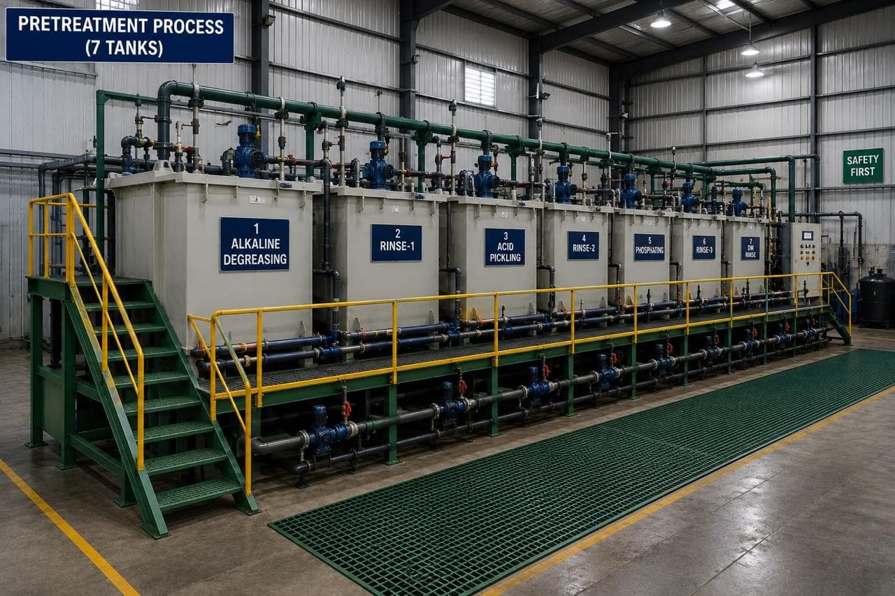
Welded cabinets, doors and gland plates go through the 16 ft × 16 ft shot blast chamber where the specification calls for a profile, then the seven-tank pretreatment line described in degreasing before powder coating, then the 18 ft × 14 ft electrostatic powder booth and the curing oven. Labour time on masking is real, and we quote it: studs, threads, gland lands, hinge faces and bonding pads are taped before the booth and verified after cure.
We build control cabinets and elevator sheet metal for TKE and Eros Elevators. The enclosure is one line in that supply; the cabinet range, including controller enclosures, is described under elevator sheet metal parts, and the panel-cutting side of the work is covered in laser cutting for electrical enclosure panels. Coating capability sits under paint shop.
What the lift drawing has to settle
- IP rating with the test method, stated for the assembled panel rather than for the empty box.
- Door gap and gasket land flatness, with the gasket section and its compression range.
- Earth bonding points, marked as masked on the finish schedule, with the bond resistance to be achieved.
- Cable entry: plate size, gland pattern, and whether blanks are cut or knocked out.
- Thermal provision: louvre area, fan cutout size, or the fixing pattern for a heat exchanger.
- Mounting plate: thickness, fixing slot pattern and whether it is fitted or shipped loose.
- Hinge and latch type, with the swing direction and the door hold-open requirement.
- Finish: pretreatment, powder type, colour, DFT range, and the masking schedule.
- Lifting and packing, because a 39 kg blank becomes an 80 kg cabinet once the plate and door are fitted.
The RFQ checklist carries most of these fields, and it is quicker than an email thread that starts with "what IP rating do you need".
Where this route stops
We fabricate and coat the enclosure. We do not fit drives, wire the panel, or issue the declaration of conformity that an assembly standard requires — IEC 61439-1 governs the assembled low-voltage controlgear assembly, and that responsibility stays with the panel builder who puts the components in.
We also do not carry out type testing to IEC 60529. We build the sealing features — gasket lands, gland plates, louvre protection and door flatness — to the rating the drawing asks for, and the rating is demonstrated on the assembly by the party that holds the certification. Where a customer wants a witness test, the enclosure is available for it before dispatch; the test itself is not ours to run.
The last limit is size. Above roughly 2.5 m in height, a welded cabinet becomes a handling and distortion problem rather than a sheet metal one, and a bolted frame or a site-assembled design is the better route. We will say so before quoting a welded box that will not stay square.
Frequently asked questions
What sheet thickness is used for a lift controller cabinet?
1.5–2.0 mm CRCA for the body and 1.5–2.0 mm for the door, with 2.5–3.0 mm for the mounting plate. Thinner than 1.5 mm the door drums and the gasket land loses flatness.
Does the enclosure need to be IP rated?
The lift specification decides. A machine-room cabinet is usually IP2X, which is finger-proof, while a machine-room-less or outdoor installation may call for IP54. We build the sealing features; the rating is proved on the assembled panel by test.
Why does the door have to be masked at the earth stud?
Powder coat is dielectric. An earth stud buried under 80 µm of cured powder reads open on a bond tester, so the stud, its land and the mating face on the body are masked and checked at under 0.1 Ω.
Can you supply the enclosure with the panel drilled and fitted?
We supply the fabricated, coated enclosure, and the mounting plate to the drawing. Component fitting and wiring stay with the panel builder, because the assembly carries its own standard and its own verification.
Sources and further reading
- IEC 60529 — Degrees of protection provided by enclosures (IP code) · reviewed 3 Nov 2026
- IEC 61439-1 — Low-voltage switchgear and controlgear assemblies, general rules · reviewed 3 Nov 2026
- ISO 2768-1 — General tolerances for linear and angular dimensions · reviewed 3 Nov 2026
Have a controller cabinet drawing?
Send the enclosure drawing with the IP rating, cable entry layout and earth bonding points. We will review the door, gasket and masking details before quoting.
Request a quote