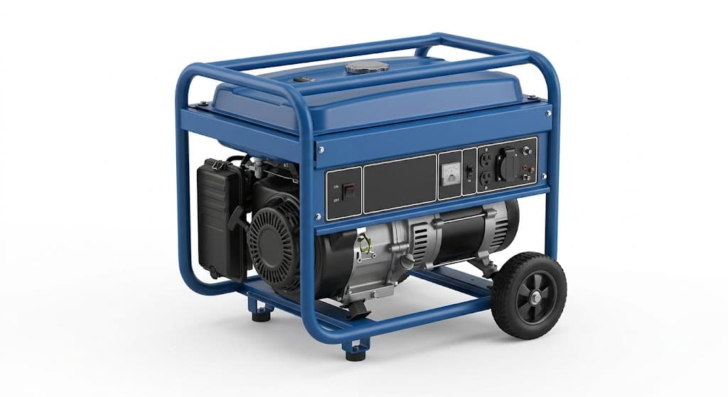
Key takeaways
- Size the tank on hours, not litres: a 240 L gross tank carries 216 L usable, which is 12.9 hours at full load for an 80 kW set burning 16.8 L/h.
- Keep leak testing at 0.2 bar: 0.3 bar puts 24 kN on a 0.8 m² panel and bulges a 3 mm skin that was flat before the test.
- Baffles at 600 mm maximum spacing and a 25 mm vent are structural parts of the design; 216 L of diesel expands 4.1 L over a 20 K rise, and a blocked vent sends that into a seam.
- Hold the pad flatness at 0.2 mm and the frame diagonal at ±2 mm after the tank is welded, because a tank welded into a finished frame pulls the mount pads out of plane.
A genset fuel tank base is a base frame with a box welded into it, and the box holds 180 kg of diesel 100 mm above the plinth the customer poured. When it weeps, the complaint is not "the tank leaks"; it is a fuel stain on a finished floor, an environmental visit, and a canopy that has to come off the set to fix a pinhole that started at the first 20 mm of a weld run.
Genset fuel tank base manufacturing is mostly a welding and testing discipline, wrapped in a volume calculation that the drawing often gets wrong. The tank is sized on hours of running, not on a round number of litres: an 80 kW output set burning 16.8 L/h needs 216 L usable for a 12.9-hour day, and that is a 240 L gross box once 10% ullage is allowed.
Three numbers decide whether the part works. Baffle spacing at 600 mm or less, so the fuel cannot move as a single mass. A leak test at 0.2 bar, not 0.3, because the flat panels bulge before the seams fail. And a vent sized for 4.1 L of expansion over a 20 K rise, because a sealed tank finds the weakest weld rather than the vent.
What genset fuel tank base manufacturing has to hold, and what the frame carries
The capacity calculation is the first thing to fix, because everything else follows from the box size. Take a 100 kVA set at 0.8 power factor: 80 kW of electrical output. A specific fuel consumption of 0.21 L/kWh at full load gives 16.8 L/h. A 240 L gross tank with 10% left for expansion and the dip tube clearance holds 216 L usable, which is 12.9 hours at full load and considerably longer at the 60–70% load a site usually runs.
Mass follows the volume. Diesel at 0.84 kg/L makes 216 L weigh 181 kg. The tank shell, in 3 mm plate over a 1,000 × 800 × 300 mm box, has about 2.68 m² of surface and weighs 2.68 × 0.003 × 7,850 = 63 kg before baffles and the frame. Add the frame, say 90 kg, and the filled base is around 335 kg on four mounts, or 84 kg per mount — which is the number the anti-vibration mount is selected on, not the dry mass.
The structural question is not the shell stress but its deflection. Under 250 mm of diesel the bottom panel sees 0.25 × 840 × 9.81 = 2,060 Pa, or 0.00206 MPa. For a 3 mm plate on an 800 mm span, simply supported, the maximum stress is about 0.287 × p × b²/t² = 0.287 × 0.00206 × 800² / 3² = 42 MPa, which is nothing against a 250 MPa yield. The deflection is not nothing: δ ≈ 0.0443 × p × b⁴ / (E t³) = 0.0443 × 0.00206 × 800⁴ / (206,000 × 27) = 6.7 mm.
A 6.7 mm bulge on the bottom of a tank that sits on a flat frame is a contact point, a wear patch and a rust start. That is why the baffles and the bottom stiffeners are structural: a 50 × 50 × 5 angle at 400 mm centres under the bottom panel cuts the effective span to 400 mm, and the deflection falls with the fourth power of that span, to roughly 0.4 mm.
The dimensions that go on a tank base drawing
The table is the specification we build to for an integral tank base, with the reason behind each line.
| Element | Typical value | Ganesh limit or note | Consequence if missed |
|---|---|---|---|
| Usable volume | 216 L from a 240 L gross box | Sized from L/h at full load, not a round figure | Refuelling stops mid-shift |
| Shell plate | 3 mm CRCA or E250 | 3 mm up to 1,500 mm long, 4–5 mm at corners | Distortion and bulging |
| Baffle spacing | 600 mm maximum | Baffles on three sides, 50 mm transfer hole at the bottom | Fuel slosh and sender swing |
| Baffle vent | 25 mm at the top | Cut before welding, not drilled after test | Air locks and slow filling |
| Vent line | 25 mm bore with a flame arrestor | Routed above the filler neck | 4.1 L expansion pressurises the tank |
| Filler neck | 50 mm above tank top, spill lip | Positioned for the canopy door | Spill runs into the base |
| Dip tube | 25 mm above the tank floor | Cut square, notched to avoid a flat seat | Water and sediment drawn in |
| Drain plug | M20 with a bonded washer | Lowest point, accessible | Water stays in the tank |
| Earth boss | M8, unpainted, welded to the shell | Masked before coating | Static discharge risk |
| Leak test | 0.2 bar air, 15 minutes, soap on all seams | Held in a fixture during test | Bulged panel or a missed pinhole |
| Pad flatness | 0.2 mm over each pad | Checked after the tank is welded | Mounts preloaded in shear |
| Frame diagonal | ±2 mm on 2,400 mm | ISO 13920 class A allows ±4 mm here, so it is a specific callout | Set sits twisted |
| Weld quality | 3 mm fillet, ISO 5817 level C | Robotic where the joint is reachable | Weeping at the start-stop |
| External finish | 80–100 µm powder | Seven-tank pretreatment and powder booth | Rust at the bottom seam |
| Internal finish | Bare, or an OEM-specified fuel-resistant coating | Not standard powder | Filter and injector damage |
Cutting, forming and the box that has to be square
The shell panels are cut on the 12 kW fibre laser, which handles 3 mm CRCA at 8–12 m/min with a kerf under 0.3 mm. The important cut on a tank is not the outline; it is the baffle slots and the corner reliefs. A corner that is cut square and welded as a butt needs a backing bar and a full-penetration weld; a corner with a 3 mm bend relief and a folded flange gives a lap that welds from outside with less distortion and no backing.
Folding the shell on the 200 T, 5-axis brake with its 4,450 mm bed produces an open box in one piece for tanks up to about 2,000 mm long, which removes two vertical seams and two of the four leak paths. The end panels are then welded in, and the baffles are slotted and welded in place before the last end goes on, because a baffle cannot be fitted through a 300 mm deep box once it is closed.
Squareness matters more than a frame fabricator expects. The tank has to drop into the base frame and the filler neck has to line up with the canopy door, so the box diagonal is held to ±2 mm. A tank that is 3 mm out on the diagonal will still bolt down, but the filler sits 2 mm off centre and the door seal rubs.
Welding 3 mm plate without a weep
A 3 mm lap or fillet joint welds at 90–110 A with a 0.8 mm wire in MIG, and the failure mode is always the same: the first 20 mm of a run, where the arc has not yet reached travel speed, sits cold and leaves a 0.3 mm gap under the toe that soap finds and dye does not. The fixes are procedural. Start every run 20 mm back from the corner and run out over the previous bead, so the cold start lands on sound metal. Keep the earth return on bare steel, because a return clamped to a powder-coated frame gives an unstable arc and a cold start on every run.
Sequence the shell in the same way as a frame: tack the box square, weld the vertical seams in opposing pairs, then the bottom, then the top flange. A tank welded from one end to the other pulls 1–2 mm out of square over 1,000 mm, and the baffles then fight the shell. Robotic MIG on the CLOOS cells handles the long bottom seams and the baffle fillets with a repeatable travel speed; the corners, the filler neck and the earth boss go to a manual station, where a welder can see the joint.
The filler neck is the joint that gets the least attention and leaks the most. It is a 60 mm tube welded into a 3 mm top panel with a 4 mm fillet, and it carries the filler hose load plus the weight of a nozzle. A doubler plate, 5 mm thick and 120 mm diameter, spreads that load and gives the welder a thicker section to work against. Without it, the top panel dishes around the neck and the fillet cracks at the toe.
Baffles, vent and the fill path
Baffles are what turn a box of liquid into a tank that behaves. At 600 mm spacing, a 1,000 mm long tank gets one baffle; at 1,500 mm it gets two. Each baffle is welded on three sides with a 50 mm transfer hole at the bottom so the fuel can equalise, and a 25 mm vent at the top so the space above the liquid is continuous. A baffle welded on all four sides with only a bottom hole turns each compartment into a separate tank that fills slowly and traps air.
The vent calculation is worth doing once. Diesel expands at about 0.00095 per kelvin. A 216 L tank that warms from 25 °C to 45 °C in a canopy in May gains 216 × 0.00095 × 20 = 4.1 L of volume. In a sealed tank that expansion has nowhere to go, and the seam that yields is the one with the least penetration. A 25 mm vent with a flame arrestor passes that volume in seconds, and it also lets air in as the engine draws fuel, which is what stops a 25 mm dip tube from cavitating at full load.
The fill path has three rules. The filler neck sits at least 50 mm above the top of the tank so a spill does not run into the base. The vent terminates above the filler so a brim-full tank pushes fuel out of the filler rather than the vent. And the dip tube stops 25 mm above the floor, so water and sediment that collect at the drain plug are not drawn into the filter.
Coating a tank, inside and out
Externally, the tank base gets the same route as the rest of the canopy: shot blast, seven-tank pretreatment, powder at 80–100 µm in the 18 ft × 14 ft booth. The bottom panel and the seams are the coating-critical areas because that is where water sits, and a tank base in a coastal installation is a C4 environment under ISO 12944-2, which is where a 60 µm film stops being enough.
Internally, standard powder is the wrong answer. A thermoset film on the inside of a fuel tank is exposed to diesel on one side and to nothing on the other, and where it lifts at a weld it becomes a flake in the filter. Internal faces are left bare, which is what most engine OEMs specify for a mild steel day tank, or given a fuel-resistant coating that the OEM names; that coating is quoted as a separate process and proved on a first article.
The earth boss and the mount pads are masked before the booth. A tank that is earthed through a 90 µm powder film is not earthed, and the first sign is a static discharge when a delivery hose is connected.
What the inspector checks before the tank leaves
Six checks release a tank base. The leak test comes first: 0.2 bar air, soap on every seam, 15 minutes, no bubbles, and a record of the gauge reading at start and end. Then wall thickness at four points on the shell and two on the baffles, because a 3 mm plate that has been ground at a seam is no longer 3 mm.
The volume check is a fill test on the first article, with the usable volume marked from the dip tube height rather than from the top of the box. The dimensional check covers the frame diagonal at ±2 mm, pad flatness at 0.2 mm and the filler position from the canopy datum. Weld inspection follows ISO 5817 level C visually, with dye penetrant on the bottom seams of the first article. The last check is earth continuity from the earth boss to the frame, measured under 0.1 Ω, and a DFT map on the underside.
Where tank bases fail in service
A weep at a weld start. A 20 mm cold start on a 3 mm lap holds pressure and fails a year later. The soap test finds it if the test is done before coating, and never afterwards.
A blocked vent. Mud dauber wasps block a 25 mm vent in a season in rural installations, and the tank then breathes through the filler cap or the seam. A cap with a small vent hole, or a vent that terminates inside the canopy with a screen, is the fix.
No baffle, or a baffle with no transfer hole. The fuel moves as one mass, the sender swings, the low-fuel alarm trips on a corner, and the base frame sees a dynamic load it was not designed for.
Water in the bottom. Condensation over a monsoon puts 2–5 mm of water in a part-full tank. Without a drain plug at the lowest point and a dip tube that stops above the water layer, the first cold start pulls it into the filter.
Coating on the earth boss. Continuity fails at commissioning, and the electrician scrapes paint off a finished tank in the field.
A filler neck with no doubler. The top panel dishes, the fillet cracks, and the leak appears at the one place a customer fills the tank.
The line that builds tank bases
Tank bases run through the same plant as the rest of the genset enclosure at Ganesh: shells and baffles cut on the 12 kW fibre laser, folded on the 200 T, 5-axis brake with its 4,450 mm bed, welded in fixtures built in our own tool room on three CLOOS robotic MIG cells or one of more than 30 manual stations, then blasted, pretreated and powder coated in-house. Leak testing happens before coating, on the frame that will carry the tank, and the record travels with the serial number.
We build base frames, skid bases and canopy kits for Mahindra Powerol, and a tank base is quoted with the frame and the canopy it sits under rather than as a loose box, because the filler position, the vent route and the mount pads are set by all three. The parts are catalogued under genset parts.
The frame underneath is covered in genset skid base design, the weld detail in welded genset base frames, and the full process route in how a genset base frame is manufactured. Canopy, louvre and base frame guides are collected under genset, canopy and acoustic enclosures, and the canopy RFQ checklist lists the fields an enquiry needs.
What to put on the drawing
- Usable capacity and the full-load consumption it is sized against, in L/h.
- Shell and baffle plate thickness, material grade and the corner detail.
- Baffle positions, transfer hole size and vent hole size.
- Filler neck position, height above the tank top and doubler plate size.
- Vent bore, route, termination height and flame arrestor requirement.
- Dip tube height above the floor, drain plug position and sender boss.
- Leak test pressure, hold time and the record required.
- Earth boss location and the continuity value.
- External finish and DFT, and the internal finish decision.
When a tank base is the wrong product
A tank base integrates fuel into the skid, and that is not always what a site wants. Above a few hundred litres the storage becomes a licensed activity under the Petroleum Rules, and the licence question belongs to the site owner, not to the fabricator. Sets that run continuously on a bulk tank are better served by a separate day tank on a stand, with the base frame carrying only the set.
Where the fuel is not diesel, the tank rules change: petrol, biodiesel blends above B20 and used oil all attack different seal and coating materials, and a tank built for diesel should not be repurposed without the OEM's confirmation. And where the customer wants a tank that is also a pressure vessel or is filled under pressure, that is a different design code with a different test regime.
Send the capacity, the consumption and the filler position with the frame drawing. Request a quote
Frequently asked questions
How many hours of fuel should a genset base tank hold?
Eight to twelve hours at full load is the usual day-tank target. An 80 kW output set burns about 16.8 L/h at 0.21 L/kWh, so 216 L usable gives 12.9 hours; anything longer is a bulk storage question rather than a base tank.
What plate thickness is used for an integral fuel tank base?
3 mm is normal for tanks up to about 1,500 mm long, with 4–5 mm at the corners and around the filler. Thinner plate distorts under welding and bulges under 250 mm of diesel head.
How is a genset fuel tank tested for leaks?
A low-pressure air test at 0.2 bar with soap solution on every seam for 15 minutes, or a hydrostatic test filled with water. The pressure limit matters: 0.3 bar puts 24 kN on a 0.8 m² panel and can permanently bulge a 3 mm skin.
Does the fuel tank base need baffles?
Yes, at 600 mm maximum spacing. Without baffles, 181 kg of diesel moves as one mass when the set is transported or the trailer brakes, and the level sender swings far enough to trip a low-fuel alarm.
Can the inside of the tank be powder coated?
No. Standard powder is not a fuel-resistant lining and flakes become a filter and injector problem. Internal faces are left bare or given a fuel-resistant coating specified by the engine OEM, and that is quoted separately.
Sources and further reading
- ISO 5817:2014 — Quality levels for imperfections in fusion-welded steel joints · reviewed 3 Nov 2026
- ISO 13920:2023 — Welding, general tolerances for welded constructions · reviewed 3 Nov 2026
- ISO 12944-2:2017 — Classification of atmospheric corrosivity of environments · reviewed 3 Nov 2026
Quoting an integral tank base?
Send the capacity, engine consumption, filler position, vent route and finish. Baffles, test pressure and pad flatness are settled before pricing.
Send a drawing